Facebook
 Google
 GitHub
 Linkedin
An Introduction to Bundled Conductors in Transmission Lines
This article explores the design of bundled conductors for high-voltage transmission lines, highlighting their electrical and mechanical advantages.
Bundled conductors consist of two or more sub-conductors per phase separated by non-conductive spacers. This arrangement significantly improves the performance of long-distance transmission lines, particularly those operating above 220 kV. As a result, bundling is a widely adopted design strategy in extra-high voltage (EHV) and ultra-high voltage (UHV) transmission systems.
In this article, we'll discuss the design and implementation of bundled conductors. First, however, let's learn more about how and why they're used.
Purpose and Benefits of Bundled Conductors
One of the primary motivations for adopting bundled conductors is the mitigation of corona discharge. Corona occurs when the electric field intensity around a conductor exceeds the breakdown strength of air, resulting in ionization and the release of energy in the form of light, heat, and sound. This not only leads to power loss but also generates broadband electromagnetic interference (EMI) that can severely impact nearby communication systems.
By using multiple sub-conductors spaced at uniform intervals, we increase the effective radius of the conductor bundle. This lowers the electric field intensity at the surface of each sub-conductor, which in turn reduces the onset and severity of corona discharge. The benefits are particularly pronounced under moist or polluted atmospheric conditions.
Another key benefit is the reduction of the line's inductive reactance. Bundling increases the geometric mean radius of the phase conductor, which directly lowers its inductive reactance per unit length. The result is reduced reactive power drop along the line, allowing better voltage regulation and improved power transfer capability. This is particularly beneficial for long transmission lines, where reactive impedance would otherwise limit the maximum transmissible power.
Finally, bundled conductors contribute to the reduction of line losses by lowering AC resistance and minimizing the impact of the skin effect. The skin effect, in which AC current crowds toward the conductor's surface, increases resistance at high frequencies—especially in large conductors. Using multiple smaller conductors in a bundle increases the surface area available for current flow, helping to mitigate this effect.
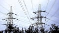
Collectively, these factors contribute to enhanced transmission efficiency, reduced conductor temperature rise, and improved overall system stability. Figure 1 shows an example of a transmission system that uses bundled conductors.
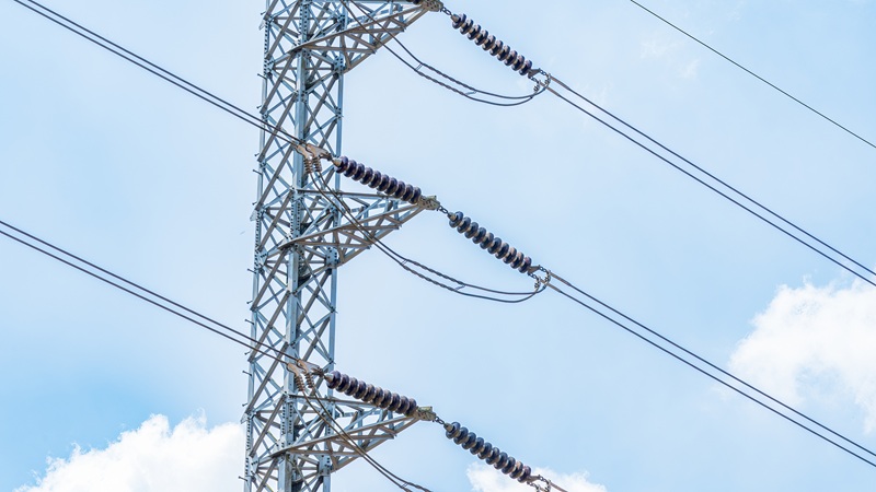
Figure 1. Bundled conductors consist of two or more sub-conductors per phase. Image used courtesy of Adobe Stock
Configuration and Phase Arrangements
The configuration of a bundled conductor is typically chosen based on the voltage class and required power handling. Common arrangements include two, three, four, or even up to eight sub-conductors per phase. Table 1 gives some examples.
Table 1. Common bundle configurations.
| Voltage Level (kV) | Common Bundle Configuration |
| 220–400 | 2 or 3 sub-conductors |
| 500–765 | 4 or 6 sub-conductors |
| 1000+ (UHV) | 6 or 8 sub-conductors |
The number of sub-conductors per phase is selected based on a trade-off between improved electrical performance and mechanical complexity. Considerations such as wind loading, ice accretion, and right-of-way constraints should all be taken into account.
Typically, each sub-conductor in a bundle is separated by 30 to 45 cm. Specially designed, non-metallic spacers maintain uniform spacing and prevent mechanical interactions. As we'll discuss in the next section, spacers are essential to maintaining the integrity and geometry of the conductor bundle.
Spacer Design and Mechanical Considerations
The spacer design must account for both axial and radial mechanical stresses. Proper spacer placement ensures symmetrical current distribution across sub-conductors and maintains the desired electromagnetic field profile, which is critical for reducing EMI and corona-related losses.
Spacers are typically constructed from composite materials such as fiberglass-reinforced polymers, which provide high mechanical strength while maintaining electrical insulation. These devices are strategically placed at intervals of 30 to 100 meters along the transmission span to prevent clashing of sub-conductors due to wind-induced oscillations, galloping, or electromagnetic forces during fault currents.
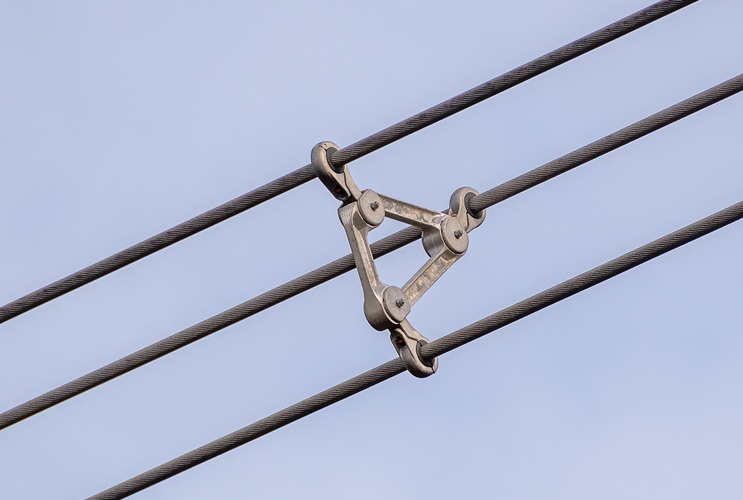
Figure 2. Spacers are used to keep the conductors apart from each other. Image used courtesy of Adobe Stock
Bundled conductor systems require sophisticated tension balancing and hardware arrangements. For example, dead-end assemblies and suspension clamps must accommodate multiple conductors without creating differential sag or torsional stress. The overall structural design must ensure that these components can withstand both static and dynamic loading under extreme weather and short-circuit conditions.
Key Takeaways
Bundled conductors are an important part of designing efficient, reliable high-voltage transmission systems. Their implementation enables significant reductions in corona discharge, inductive reactance, and AC resistance—factors that directly influence power losses, voltage stability, and overall transmission capacity. Optimizing conductor configuration is part of what enables EHV and UHV networks to deliver power over vast distances with minimal losses and maximal performance.