Facebook
 Google
 GitHub
 Linkedin
A Guide to Electromagnetic Interference in High-Voltage Transmission Lines
The article explores the issue of electromagnetic interference (EMI) in high-voltage transmission systems, highlighting its sources, impacts, and the mechanisms through which it spreads.
Electromagnetic interference (EMI) is a major concern in high-voltage transmission systems. Figure 1 illustrates the electromagnetic fields that form around a high-voltage transmission line.
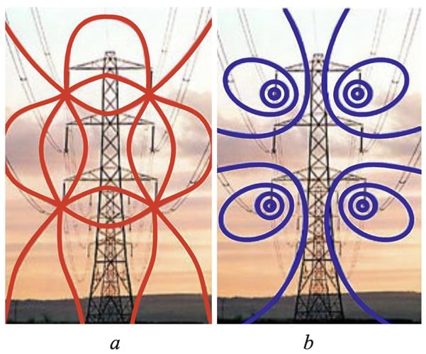
Figure 1. The magnetic (a) and electric (b) field in a high-voltage transmission line. Image used courtesy of B. Alameri (via Academia)
EMI can cause significant disruption to both communication systems and sensitive electronic equipment near power lines or electrical substations. Understanding EMI—what causes it, how it affects systems, and how to mitigate those effects—is crucial for ensuring the reliability and efficiency of modern power grids.
Sources of EMI in Transmission Systems
EMI in transmission systems can have several different origins. Each contributes to the disturbance of nearby systems in different ways.
Switching Transients
Switching transients are high-frequency voltage spikes that result from the rapid opening or closing of relays, circuit breakers, or other switching devices in the electrical grid. These transients are characterized by their sudden onset and rapid decay, and are often accompanied by sharp voltage and current fluctuations.
Switching transients are a major source of high-frequency noise, propagating along the transmission lines and radiating electromagnetic energy into the surrounding environment. The magnitude of these transients depends on factors such as the switching speed, the type of equipment used, and the characteristics of the transmission lines.
Harmonics
Harmonics are distortions in the power supply that arise when nonlinear loads, such as transformers, variable-speed drives, and rectifiers, draw a non-sinusoidal current. These nonlinear currents create harmonic frequencies that superimpose on the fundamental frequency, which is usually 50 or 60 Hz.
Harmonics are particularly problematic as they can interact with other electrical systems, including communication equipment and sensitive instrumentation. The presence of harmonics can also lead to equipment overheating, reduced power quality, and circuit malfunction.
Corona Discharge
Corona discharge is a phenomenon that occurs on high-voltage transmission lines due to the ionization of air around the conductors. This discharge results in the generation of high-frequency electromagnetic waves that can radiate into the surrounding space. The severity of corona-related EMI is influenced by the diameter, surface condition, and voltage level of the conductor, as well as by environmental conditions such as temperature and humidity.
Corona discharge also leads to electromagnetic noise emissions. These can interfere with nearby communication systems, particularly in the VHF and UHF bands.
System-Level Impacts of EMI
The impacts of EMI on electrical and communication systems are significant. As we'll see in this section, they range from degraded performance to complete system failure.
Interference with Communication Systems
EMI can disrupt communication signals by inducing noise in the transmission lines, which causes distortion in the signal. For example, in radio communications, EMI can manifest as interference in the form of static, fading, or complete signal loss.
In power transmission systems, this becomes especially problematic in densely populated areas, where both power lines and communication infrastructure are closely located. The interference may extend over several kilometers, depending on the frequency and strength of the EMI.
Disruption to Sensitive Electronic Equipment
Modern electronic equipment is highly sensitive to EMI. This is particularly true of the equipment used in the control, protection, and automation of power systems. There, EMI can lead to relay mis-trips, erroneous readings from measurement devices, or even complete failure of systems due to induced voltages.
Additionally, the growing integration of power systems with information technology and networked devices has increased the susceptibility of these systems to interference. Even small fluctuations or disturbances can lead to significant errors in these critical systems, affecting the overall stability of the grid and causing economic losses.
Coupling Mechanisms of EMI in Transmission Environments
A critical aspect that governs the severity of EMI in transmission systems is the mode of coupling—that is, how interference travels from the source to the victim system. Figure 2 illustrates the three primary coupling mechanisms in power transmission systems.

Figure 2. EMI coupling modes. Image used courtesy of Wolfspeed
Let's briefly discuss each of these.
Conductive Coupling
Conductive coupling occurs when EMI is transferred directly through physical connections such as shared grounding systems or neutral conductors. This is particularly significant in substations or control rooms where signal and power circuits may share a common earth reference. If not properly isolated or bonded, interference currents can propagate through ground paths, leading to noise in protective relays or measurement equipment.
Capacitive Coupling
Capacitive coupling occurs when two conductors at different potentials are in close proximity, allowing displacement current to flow through the parasitic capacitance between them. In high-voltage environments, such coupling can induce unwanted voltages in parallel control cables, especially those running along transmission towers or overhead ground wires (shield wires). The risk is exacerbated in dry weather, when surface leakage paths are minimal and capacitive effects dominate. Capacitive coupling is also known as electrostatic coupling.
Inductive Coupling
Also known as magnetic coupling, inductive coupling arises when a time-varying magnetic field—such as that from a transient current or fault arc—induces a voltage in a nearby conductor loop. This is one of the dominant EMI mechanisms for long-line communications or SCADA cables routed near high-current-carrying phases. The magnitude of the induced voltage depends on the mutual inductance and the rate of change of current (di/dt), which can be severe during switching or lightning events.
Design Approaches to Minimize EMI
In this section, we'll discuss several design strategies aimed at mitigating EMI in transmission systems. When applied in concert, these strategies serve to minimize the sources of interference and reduce the coupling of electromagnetic fields into vulnerable systems.
Shielding
Shielding, in the form of conductive barriers around transmission lines or sensitive equipment, helps to block the propagation of electromagnetic waves. Transmission lines can be shielded by wrapping the conductors with grounded metallic layers, which absorb or reflect the electromagnetic waves before they reach nearby communication systems. Similarly, electronic equipment can be placed in enclosures made of conductive materials (metal cases or Faraday cages) that shield them from external EMI.
Grounding Practices
Proper grounding is essential for controlling EMI. Grounding provides a path for unwanted currents or noise to flow safely into the earth, reducing the likelihood of interference with sensitive equipment. A good grounding system ensures that electromagnetic energy doesn't accumulate on equipment or structures, preventing the build-up of interference and reducing the potential for damage to electronic systems.
Filters
Filters are widely used in transmission systems to eliminate or attenuate unwanted frequencies. Power filters can be installed at key locations, such as at the inputs and outputs of equipment, to block harmonic frequencies and other high-frequency noise generated by switching transients and corona discharge. Filters can also be used to suppress specific frequency bands where EMI is particularly problematic.
The effectiveness of a filter depends on its design and the frequency range it targets. The choice of whether to use low-pass, high-pass, or band-pass filters is made based on the characteristics of the EMI in the system.
Line Routing and Placement
Careful routing of transmission lines and communication cables is another technique used to minimize EMI. By increasing the physical separation between power lines and communication systems, the risk of coupling is reduced. Additionally, the ground provides a natural shield against electromagnetic waves. Routing power lines underground, where feasible, can therefore significantly reduce the likelihood of radiated EMI.
The placement of equipment such as transformers and switchgear also plays a role in minimizing EMI. Proper placement serves to isolate sensitive systems, such as communication and control equipment, from high-impedance and high-voltage areas.
Key Takeaways
Electromagnetic interference in modern transmission systems arises from a variety of sources, including switching transients, harmonics, and corona discharge. The consequences can be severe, with EMI leading to disruptions in communication systems and malfunctions of sensitive electronic equipment. However, the design approaches we discussed in this article—shielding, grounding, filtering, and strategic line routing—can effectively mitigate EMI and ensure the proper functioning of both power and communication systems.
Featured image used courtesy of Adobe Stock