Facebook
 Google
 GitHub
 Linkedin
Transmission Line Losses and Efficiency Optimization—Part 2
Learn how frequency impacts transmission line parameters—resistance, inductance, capacitance, conductance—due to skin/proximity effects, affecting efficiency and long-distance HVAC performance.
Check out Part 1 of this article series.
This article explores the frequency-dependent behavior of transmission line parameters, emphasizing the impact of skin and proximity effects on resistance and efficiency. It also examines how these phenomena, along with reactive power dynamics, affect long-distance HVAC transmission performance.
Transmission line parameters—resistance, inductance, capacitance, and conductance—vary with frequency due to physical effects like skin and proximity effects, which increase AC resistance by forcing current to flow near the conductor surface and in uneven distributions. This leads to higher power losses and affects inductive behavior.
Capacitance and dielectric losses also change slightly with frequency, particularly under high-frequency transients. In long-distance HVAC transmission, these frequency-dependent effects cause real and reactive power losses, voltage regulation issues, and reduced system stability. HVDC transmission offers a more efficient alternative over long distances by avoiding reactive power and maintaining lower losses.
Frequency Dependency and Skin Effect in Transmission Lines
The electrical characteristics of transmission lines—resistance (R), inductance (L), capacitance (C), and conductance (G)—are not constant over frequency. While these parameters are typically treated as fixed under steady-state sinusoidal operation (for example., 50 Hz or 60 Hz), in real systems they exhibit frequency dependency due to the distributed nature of transmission lines and the non-ideal behavior of conductors and dielectrics.
This frequency-dependent behavior becomes particularly relevant in high-frequency transient studies, switching operations, harmonics analysis, and the design of UHV and long-distance EHV transmission lines.
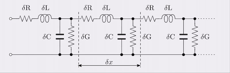
Figure 1. Transmission Line Parameters. Image used courtesy of Steemit.
Skin Effect
One of the most critical manifestations of frequency dependency in conductors is the skin effect, a phenomenon where alternating current (AC) tends to concentrate near the outer surface of a conductor as frequency increases. This is caused by the interaction between the time-varying magnetic field produced by the AC and the induced eddy currents inside the conductor, which oppose the current flow in the core region due to Lenz’s Law.
The effective penetration of current into the conductor is quantified by the skin depth δ, given by:
$$\delta = \sqrt{\frac{2 \rho}{\omega \mu}} = \sqrt{\frac{2 \rho}{2 \pi \mu}} = \sqrt{\frac{\rho}{\pi \mu}} $$
Where:
- δ: Skin depth (m)
- ⍴: Electrical resistivity of the conductor material (Ω·m)
- ƒ: Frequency of the AC current (Hz).
- µ: Absolute magnetic permeability of the conductor (H/m), µ = µ0 µτ.
- µ0: Permeability of free space (4π × 10-7 H/m)
- µτ: Relative permeability of the material
As frequency increases, the skin depth δ decreases, meaning the current is confined to a thinner outer layer of the conductor. For copper at 60 Hz, the skin depth is approximately 8.5 mm. At 1 kHz, it reduces to about 2 mm.
This leads to an increase in the effective AC resistance of the conductor compared to its DC resistance. The AC resistance Rac can be several times greater than the DC resistance Rdc , depending on the frequency and geometry. For large conductors, this can be approximated as:
$$R_{ac} \approx R_{dc} \cdot \big( 1 + {\frac{t}{\delta}} \big)$$
Where t is the thickness of the current-carrying layer (often the conductor radius for round wires).
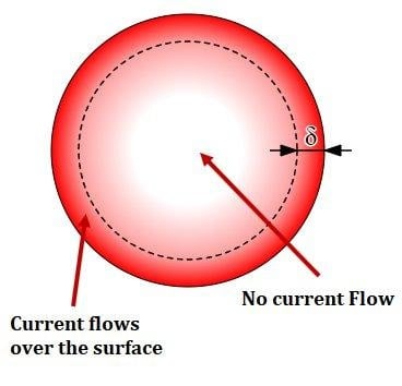
Figure 2. Skin effect in a conductor. Image used courtesy of Wikipedia.
Implications of Skin Effect in Transmission Lines
The increase in AC resistance due to skin effect results in higher I2R losses, thereby reducing the efficiency of power transmission. For high-capacity or long-distance lines operating under significant harmonic content or high switching frequencies, this is non-negligible.
Moreover, the non-uniform current distribution modifies the internal inductance of the conductor. In ideal conditions, inductance consists of internal and external components:
$$L = L_{internal} + L_{external}$$
With increasing frequency, Linternal → 0 due to current confinement to the outer layer, leading to slightly higher total inductive reactance X = ωL.
This frequency-sensitive behavior requires the use of bundled conductors in high-voltage transmission lines. Bundling increases the effective surface area and helps mitigate skin effect and associated resistance rise.
Proximity Effect and Its Relationship to Frequency
Closely related to skin effect is the proximity effect, which arises when conductors are placed near each other (for example, in three-phase systems or multi-conductor bundles). The magnetic fields of adjacent conductors cause the current distribution in each conductor to become uneven, concentrating it further on the sides facing neighboring conductors.
The proximity effect is also frequency-dependent, intensifying at higher frequencies due to stronger time-varying fields. In bundled conductors, this effect is partly offset by transposition and spacing optimization.
In practical power transmission, both skin and proximity effects are considered in calculating effective resistance per unit length using empirical or numerical models. These corrections are implemented in line modeling software such as PSCAD, EMTP-RV, and PowerFactory for accurate simulation under steady-state and transient conditions.
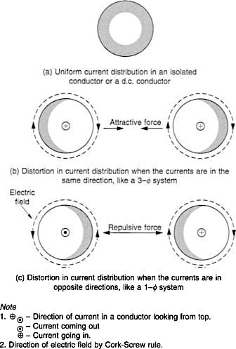
Figure 3. Proximity effect in round conductors. Image used courtesy of ScienceDirect.
Frequency Effects on Capacitance and Dielectric Loss
While less pronounced than resistance and inductance, the line capacitance may also exhibit frequency-dependent behavior, especially over a wide spectrum. The permittivity of insulation materials (such as air, SF₆, or polymeric cable insulation) can vary with frequency due to dielectric dispersion.
Additionally, dielectric losses, modeled by the conductance G, tend to increase at higher frequencies, although this is typically minor at 50–60 Hz unless the insulation is poor or aged.
This becomes more critical in high-frequency transients such as lightning impulses or switching surges, where capacitive behavior dominates and may lead to resonance phenomena.
| Parameter | Frequency Dependency | Impact |
| Resistance (R) | Increases (due to skin and proximity effects) | More real power loss |
| Inductance (L) | External L constant; internal L decreases | Higher reactance |
| Capacitance (C) | Slight variation due to permittivity changes | Voltage oscillations in transients |
| Conductance (G) | Increases slightly | Insulation losses |
Modeling and Mitigation Strategies
Advanced transmission line models (such as frequency-dependent π or Bergeron models) are required to capture the non-linear variation of line parameters across frequencies. These models are crucial for accurate time-domain analysis, especially for high-speed switching or transient stability studies.
To mitigate the adverse effects of skin and proximity effects:
- Hollow conductors or tubular buses are used in substations
- Bundled conductors reduce effective AC resistance
- Transposition helps balance inductance and reduce proximity-induced losses
- Litz wire (used in special applications like transformers or high-frequency filters) reduces skin effect, but is impractical for bulk power transmission
Frequency-dependent behavior and the skin effect represent fundamental physical phenomena that impact the performance, loss profile, and modeling accuracy of transmission lines. They are especially relevant in modern power systems, where transient conditions, harmonics, and EHV/UHV transmission pose increasing design and operational challenges.
Impact on Long-Distance Transmission Efficiency
In long-distance power transmission—typically classified as lines exceeding 250 km for HVAC systems and 100 km for HVDC—the efficiency of power delivery becomes increasingly sensitive to the line’s electrical parameters and operational conditions.
The core challenge arises from the distributed nature of resistance (R), inductive reactance (XL), and shunt capacitance (C), which collectively lead to power losses, voltage regulation issues, and reactive power imbalance.
As the transmission distance increases, these parameters not only magnify losses but also introduce resonance, stability limits, and power transfer constraints. Efficiency degradation is no longer dominated solely by resistive losses (I²R), but also by reactive power circulation and dielectric behavior across the transmission corridor.
Real Power Losses Due to Resistance
The series resistance of transmission conductors directly contributes to real power loss, which is dissipated as heat. The power loss per phase is given by:
$$P_{loss} = I^2 R_{eff}$$
Where I is the RMS line current and Reff includes corrections for AC resistance due to skin and proximity effects. For a three-phase system, total real power loss becomes:
$$P_{loss,total} = 3 I^2 R_{eff}$$
In long lines, the increase in total resistance with length leads to higher losses even at constant current. Additionally, resistance rise due to elevated conductor temperature under loading further reduces transmission efficiency.
Reactive Power Absorption and Line Charging
For high-voltage long-distance lines, reactive power behavior becomes a dominant concern. The distributed inductance (L) leads to reactive power absorption, while distributed capacitance (C), especially under light load or no-load conditions, results in reactive power generation (also known as line charging).
In a uniformly distributed line, the reactive power generated by the shunt capacitance is approximated by:
$$Q_C = \omega C V^2$$
Where ω = 2πƒ, C is total line-to-ground capacitance, and V is line voltage. For lines longer than 250 km, the charging reactive power can become significant enough to over-voltage the receiving end under no-load conditions—a phenomenon known as the Ferranti effect.
Simultaneously, inductive reactance increases with length:
$$X_L = 2 \pi f L$$
leading to greater voltage drop under load and increased requirement for reactive power support at both ends to maintain voltage profiles.
Voltage Profile and Efficiency Constraints
One of the defining limits for long-distance HVAC transmission is voltage regulation—the ability to maintain voltage within acceptable limits across sending and receiving ends. For a transmission line of length l modeled as a distributed-parameter system (using hyperbolic functions), the sending and receiving end voltages and currents are related by:
![]()
In this equation, the propagation constant, γ, is given by:
$$\gamma = \sqrt{(R + j \omega L)(G + j \omega C)}$$
The characteristic impedance equation is:
$$Z_C = \sqrt{ \frac{R + j \omega L}{G + j \omega C}}$$
The solution demonstrates that the voltage magnitudes and phase angles vary nonlinearly along the line, particularly for lengths exceeding 300 km. These variations degrade the ability to control power flow and stabilize the system under dynamic conditions, thereby reducing efficiency from both technical and economic perspectives.
Surge Impedance Loading and Stability Limits
An important parameter for evaluating long-line efficiency is Surge Impedance Loading (SIL), the power at which a line naturally balances its reactive power generation and absorption. SIL is defined as:
$$SIL = \frac{V^2}{Z_C}$$
Where V is the line voltage and Zc is the surge impedance. For a 400 kV line with Zc ≈ 300 Ω , SIL is approximately 533 MW per phase.
If a line is loaded significantly below SIL, it becomes a net reactive power source and may cause overvoltage. When loaded above SIL, it becomes a reactive sink, and voltage may sag unless supported with capacitive compensation. Operating significantly away from SIL results in increased losses due to reactive power circulation and underutilization of available transmission capacity.
Additionally, high loading causes angular stability limitations, where rotor angle differences between sending and receiving generators become large, risking system instability. These limits are dictated by the power-angle relationship:
$$P = \frac{V_s V_r}{X}\cdot \sin(\delta)$$
Where δ is the power angle and X is the total reactance. Long lines increase X, decreasing power transfer capability for a given angle and raising system vulnerability to oscillations and faults.
Comparative Advantage of HVDC for Long Distance
Due to the limitations discussed above, HVDC transmission becomes a more efficient choice for very long distances, typically beyond 600–800 km overhead or 50 km underground/submarine. HVDC eliminates reactive power flow, has lower resistive losses at equivalent voltage levels, and supports asynchronous interconnections between grids.
The power loss comparison for long HVAC and HVDC lines of the same rating clearly shows that HVAC losses escalate with line length due to cumulative reactance and charging currents, while HVDC losses scale linearly with resistance alone.
| Mode | Power Loss Mechanism | Efficiency over Long Distance |
| HVAC | I²R + charging current + reactive loss | Decreases with length |
| HVDC | I²R only | Higher and more stable |
For instance, ±800 kV HVDC systems can transmit over 6000 MW with losses under 3% over 2000 km, a figure unachievable for comparable HVAC lines. This is largely due to the inherent characteristics of DC transmission, where reactive power does not consume line capacity.
Key Takeaways
Understanding the frequency-dependent behavior of transmission line parameters, along with phenomena like skin and proximity effects, is crucial for designing and operating efficient, stable, and reliable power systems—especially in high-voltage and long-distance applications.
These effects directly impact power losses, voltage control, and system dynamics, making them vital considerations in transient analysis, harmonic studies, and transmission planning. In practical terms, accounting for these phenomena enables better conductor selection, optimized line configurations, and informed decisions between HVAC and HVDC technologies, ultimately supporting improved grid performance and the integration of modern power system demands such as renewable energy and high-capacity interconnections.
Continue reading this article series with Part 3: Ferranti Effect and Its Impact on Long-Distance High-Voltage AC Transmission Line Regulation.
Featured image used courtesy of Adobe Stock (licensed)