Facebook
 Google
 GitHub
 Linkedin
An Introduction to Surge Impedance in Long-Distance Power Transmission
In this article, we will examine surge impedance loading and voltage profiles. This is the first article of a 3-part series on long transmission line behavior.
The surge impedance, also known as the characteristic impedance Z0, is a fundamental property of long transmission lines governed by distributed parameters. It is defined as the ratio of the voltage to the current of a single traveling wave propagating along a lossless line. For a line modeled with distributed inductance L (H/m) and capacitance C (F/m), the surge impedance is given by:
$$Z_0 = \sqrt{ \frac{L}{C} }$$
This expression assumes negligible resistance and conductance, which is a reasonable approximation for high-voltage overhead lines over long distances. Physically, Z0 represents the impedance at which a line will neither reflect nor absorb a traveling wave, making it critical for understanding wave propagation and line loading behavior. The values of Z0 for typical overhead lines range from 300 to 600 ohms, depending on geometry and conductor configuration.
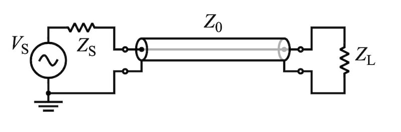
Figure 1. A schematic representation of a circuit in which a source is connected to a load via a transmission line having characteristic impedance Z0. Image used courtesy of Wikipedia.
Surge Impedance Loading (SIL)
Surge Impedance Loading (SIL) is the real power at which a transmission line naturally operates with unity power factor, meaning that the reactive power generated by the line’s capacitance is exactly absorbed by the line’s inductance. It is given by the square of the line-to-line RMS voltage divided by the surge impedance:
$$\text{SIL} = \frac{V^2_{LL}}{Z_0}$$
Where:
- VLL is the RMS line-to-line voltage,
- Z0 is the surge impedance of the line.
At the SIL point, the line draws only active power, and there is no net reactive power exchange with the system. This loading condition is crucial because any deviation from SIL—whether underloading or overloading—results in reactive power imbalance. Lines loaded below SIL act as reactive power sources, while those loaded above SIL act as sinks. This phenomenon directly impacts voltage regulation and reactive power planning across the network.
For example, a 500 kV line with a typical surge impedance of 400 Ω has a SIL of:
$$\text{SIL} = \frac{ (500 \times 10^3)^2}{400} = 625 \text{ MW}$$
This SIL value sets a benchmark for assessing loading levels and planning reactive compensation.
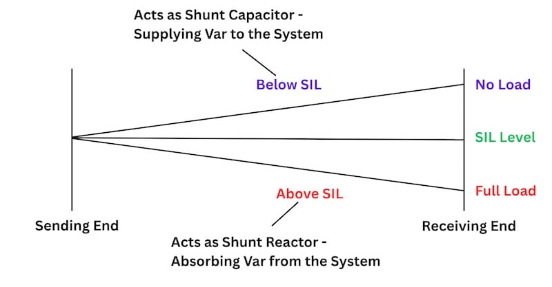
Figure 2. SIL and reactive power. Image created by the author.
Voltage Rise and the Ferranti Effect
One significant phenomenon observed in lightly loaded or open-ended long transmission lines is the Ferranti effect, wherein the receiving-end voltage exceeds the sending-end voltage. This occurs because the line’s shunt capacitance dominates under light loading, leading to capacitive charging currents that cause a voltage rise toward the line’s end. The longer the line and the higher the operating voltage, the more pronounced the effect becomes.
Mathematically, the Ferranti effect is described by the hyperbolic solution to the long line equations. If Vr is the receiving-end voltage and the line is unloaded, the sending-end voltage Vs can be expressed as:
$$V_s = V_r \cosh (\gamma l)$$
where:
- γ is the complex propagation constant,
- l is the line length.
The complex propagation constant is given by:
$$\gamma = \sqrt{ (R + j \omega L)(G + j \omega C)}$$
For low-loss lines (small R and G), γ ≅jβ, and the equation simplifies to:
$$|V_s| \approx |V_r| \cos (\beta l)$$
Since cos(βl) < 1 for lines approaching a quarter-wavelength, the magnitude of Vs can be less than Vr, leading to a voltage rise at the receiving end. This effect can pose overvoltage risks, especially for unenergized lines or during no-load switching operations.
Mitigation and Reactive Compensation
To maintain voltage stability and prevent overvoltage conditions under light-load or no-load situations, reactive compensation devices such as shunt reactors or STATCOMs are often deployed. Shunt reactors, connected at the receiving end or midpoint, absorb excess reactive power and suppress voltage rise. The selection of compensating equipment is typically based on SIL, line length, and expected operating conditions.
Moreover, understanding the SIL framework aids in long-term planning for reactive power support. Lines operating consistently below SIL may require fixed or switchable reactors, while those above SIL (heavily loaded) may need capacitor banks or dynamic VAR devices to support voltage. This interplay is especially critical in grids with high penetration of renewables, where load variability and distributed generation further complicate reactive power balancing.
Key Takeaways
In modern power systems, accurate modeling and understanding of long transmission lines are essential for ensuring both operational reliability and optimal power transfer. The distinct behavior of long lines—including distributed parameter effects, surge impedance loading, wave propagation, and angle stability—directly influences how systems respond to disturbances, load variations, and control actions.
In this first article, we have taken a look at the surge impedance. In the next two articles in this series, we will learn about wave propagation, power transfer, and angle stability.
These characteristics are not only essential to voltage profile management and overvoltage mitigation but also play a critical role in system planning, protection coordination, and the integration of renewable resources over vast distances. As grids become more interconnected and dynamic, incorporating detailed long-line models into simulation tools and stability assessments becomes increasingly vital for secure and efficient grid operation.
Coutinue readinng this series with Part 2: An Introduction to Wave Propagation in Long-Distance Power Transmission.
Featured image used courtesy of Adobe Stock (licensed)