Facebook
 Google
 GitHub
 Linkedin
High Reliability Preforms for Module-To-Heatsink Attach
Learn how Innolot 2.0 offers a cost-optimized, highly reliable solder alloy for EV power module heatsink attachment, delivering superior creep performance and reduced thermal stress.
This article is published by EEPower as part of an exclusive digital content partnership with Bodo’s Power Systems.
Power modules can be classified into two categories: Frame modules, which use plastic housing filled with silicone gel as encapsulant, and transfer molded modules (TMM), which use epoxy mold compounds (EMC) as encapsulant.
Later ones are an established choice for traction inverters in electric vehicles (EV) [1]. The reliable and cost-efficient attachment of the TMM to a heatsink is a key process in EV traction inverter assembly.
Several attachment variants exist in the market: Large area sintering (LASi) using silver- or copper- sinter pastes, large area soldering (LASo) using lead-free low-melting solder preforms, or polymer-based thermal interface materials (TIM).
Large area sintering is predominantly used for premium applications with the highest thermal and reliability requirements. Large area soldering offers a good compromise between costs, good thermal performance, and reliability.
A LASo process combining a low-melting solder alloy and a solder process based on vacuum/formic acid offers almost void-free, low-cost, and highly reliable solder joints. The alloy system must be chosen in such a way that its liquidus temperature is low and therefore compatible with the EMC, which has a typical glass transition temperature Tg from 180°C to 200°C [2].
When exceeding the Tg of the EMC during the assembly process, its coefficient of thermal expansion increases significantly, which can cause damage to the power module during the assembly process and lead to failure of the power module.
Based on that, the highest care must be taken to properly select the solder alloy and use suitable solder techniques to avoid EMC delamination from the power module.
In this contribution, the advantage of the Innolot® solder alloy family, especially Innolot2.0, will be shown based on simulation and experimental data.
The Alloy System Innolot2.0™ – A Cost-Optimized Solder Alloy for LaSo
For a successful LASo process, the alloy system should have a liquidus temperature as low as possible to limit the stress on the package by a high-temperature solder process and therefore avoid internal EMC delamination. Additionally, the alloy system must show sufficient reliability (i.e., creep properties) and must be affordable (i.e., Ag content). A non-extensive comparison of available solder alloy systems is given in Table 1.
Table 1. Material properties of various commercially available solder alloys. + means most beneficial properties, whereas – highlights non-beneficial properties.
| Innolot® 1.0 | Innolot® 2.0 | SnSb5 | SAC305 | |
| Composition | SnAg3.8Cu0.7 Ni0.1Sb1.5Bi3 |
SnAg1.5Cu0.7 Sb1.5Bi3X |
SnAg3Cu0.5 | |
| Melting range | 206-218 °C | 212-222°C | 228-243°C | 217-220°C |
| Reliability | + | + | 0 | - |
| Cost | 0 | + | + | 0 |
Innolot (here stated as Innolot 1.0) is a well-known alloy in the Tin-Silver-Copper system with small additions of Nickel, Antimony, and Bismuth for improvement of creep strength [3]. The combination of a rather low melting temperature, ranging from 206-218 °C, with increased creep strength, makes Innolot a good candidate for the large area soldering process.
However, Innolot 1.0 has a silver content of 3.8 wt%, which adds precious metal costs to the overall alloy price. Driven by the market demand, Heraeus Electronics developed a new SAC-based alloy with different additives and significantly lower Ag-content, which is commercially available as Innolot 2.0 [4].
The slightly higher melting temperature range of 212- 222°C is still well below the melting temperature range of SnSb5 (228-243°C), which makes Innolot 2.0 the cost-optimized choice for the attachment of TMMs to heatsinks. The major benefit of Innolot 2.0 is its significantly lower Ag content of only 1.5 wt%. Heraeus Electronics offers Innolot 1.0 and Innolot 2.0 alloys as ribbons and precut preforms.
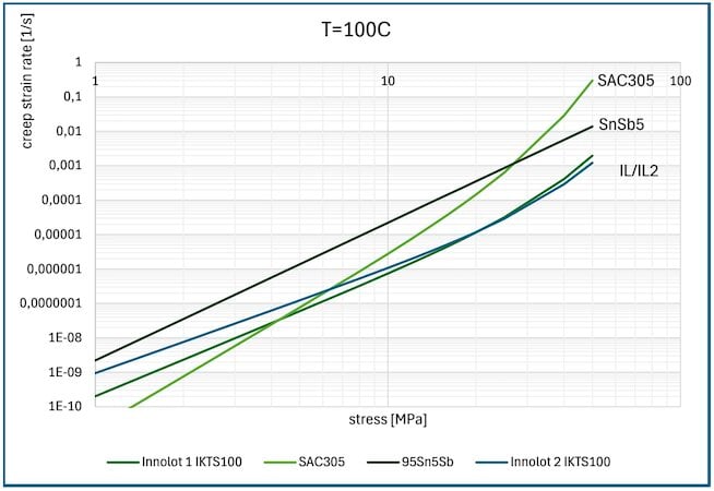
Figure 1. Fitted creep rates as a function of stress at T=100°C. The values were measured at 100 °C using test samples that were exposed to constant stress. Creep rates were extracted, and the measurement points were fitted using the Garofalo equation. Data generated in cooperation with Fraunhofer IKTS. Image used courtesy of Bodo’s Power Systems [PDF]
Superior Creep Properties and Improved Reliability
The superior creep performance and its influence on the thermal shock performance are proven by material characterization, simulation, and thermal shock tests. Figure 1 shows the fitted secondary creep rate as a function of stress of the four alloys from Table 1 using the Garofalo law.
The data is available at multiple temperatures but is only shown for T=100 °C. Full material models are available on request. The Innolot family shows the lowest secondary creep rates at the highest stress, which indicates the highest reliability in the final application, as creep is a major contributor to solder alloy degradation.
With the available material data, thermomechanical finite element simulations (FEM) of the four alloys under thermal cycling conditions were conducted. The simulation model is shown in the left and center pictures of Figure 2. Within the simulation, an AMB substrate was soldered with a 100 µm thick solder layer to an aluminum-based heatsink and molded with an EMC.
The assembly was cycled within the simulation from -40 °C to +125 °C with a dwell time of 30 min. The strain per thermal cycle was selected as a damage parameter to compare the four alloys. Figure 2 (right picture) shows a comparative heatmap of the strain per cycle within each half-bridge of the four alloys.
Clearly visible is that SAC305 and SnSb5 show higher strain per cycle compared to the Innolot family. Additionally, the highest strain per cycle (damage) occurs at the edges of the module. Based on the simulation, the Innolot alloys should show less delamination during thermal cycling than the SAC305 or SnSb5.
Additionally, the solder process of SnSb5 alone could already damage the EMC/AMB interface due to the high melting temperature range of SnSb5 compared to Innolot. This effect is not covered in the FEM simulation. The simulation study was repeated using 300 µm thick solder layers. The strain per cycle is significantly reduced. The bond line thickness is therefore another influencing factor on solder reliability, but also on cost.
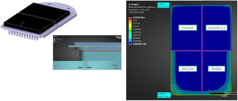
Figure 2. Left and middle pictures - Simulation model. Right picture - Creep strain per thermal shock cycle of the 4 alloys. Blue indicates the lowest strain per cycle. Red indicates the highest strain per cycle. Image used courtesy of Bodo’s Power Systems [PDF]
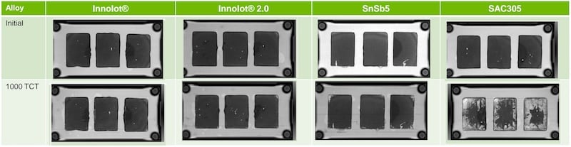
Figure 3. SAM images before and after 1000 cycles of thermal shock. Image used courtesy of Bodo’s Power Systems [PDF]
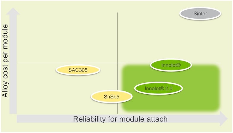
Figure 4. Ranking of the four tested alloys within the Reliability/Cost chart. Image used courtesy of Bodo’s Power Systems [PDF]
Thermal shock tests confirm this finding from the simulation. For this purpose, bare AMB substrates (0.3 mm Cu/0.32 mm Si3N4/0.3 mm Cu) were soldered to Ni-plated Cu-core baseplates (3 mm thickness). The soldered area was 27 x 38 mm2 for each AMB.
The assemblies were soldered using 300 µm thick alloy preforms under vacuum/formic acid using a PINK vadu 200 solder equipment. The individual assemblies were not molded within this study. Before and after thermal shock (-40°C/+125°C), scanning acoustic microscope (SAM) images were taken, which are shown in Figure 3.
SAC305 shows severe degradation after 1000 cycles. SnSb5 shows slight delamination at the edges of the assemblies, which matches to the simulation expectation. Innolot 2.0 shows only minor delamination on one of the assemblies, whereas Innolot 1.0 shows no visible delamination at all. The experimental thermal cycling results confirm our simulation results.
Conclusion
Innolot 1.0 and Innolot 2.0 are proven low-melting but highly reliable alloys. Our findings based on the conducted material characterizations, simulations, and experiments are summarized in Figure 4. Innolot 1.0 and Innolot 2.0 are both commercially available as individual preforms or ribbons.
This article originally appeared in Bodo’s Power Systems [PDF] magazine.