Facebook
 Google
 GitHub
 Linkedin
Variable DC-Link Voltage LLC Resonant DC/DC Converter using GaN HEMTs and SiC Diodes
As the demand for efficient DC/DC converters continues to rise, this article examines LLC resonant converters.
This article is published by EE Power as part of an exclusive digital content partnership with Bodo’s Power Systems.
Wide-range LLC resonant DC/DC converters are extensively applied in multiple scenarios, such as electric vehicle chargers and renewable energy generation. These converters are part of a two-stage power supply which consists of an AC/DC converter and an isolated DC/DC converter.
The increased penetration of EVs has brought the need to develop higher-power-density battery chargers to combat the long charging times of batteries. As the interface of grid-to-vehicle power flow, an onboard charger (OBC) operates to charge the battery bank in an EV with the power from the utility grid. Most OBCs on the market use silicon IGBTs due to reduced cost. However, the introduction of wide bandgap devices, such as gallium nitride (GaN) and silicon carbide (SiC), have low reverse recovery current and high switching slew rate, making them preferable for compact EV electric systems.
A typical OBC system comprises two stages of the circuit, a power factor correction (PFC) circuit such as a boost converter PFC, a totem-pole PFC, or a Vienna rectifier, and a galvanic isolated DC/DC converter with intrinsic zero voltage switching (ZVS) features, such as a resonant converter or a phase-shift converter. The objective of increasing the power efficiency and broadening the operation range of the DC/DC converter requires a detailed design process of a high-efficiency LLC DC/DC converter using GaN HEMTs and SiC diodes.
Specifically, Infineon CoolGaN High Electron Mobility Transistors (HEMTs) utilization at the input bridge and CoolSiC Schottky diodes at the output bridge define the design fundamentals. A new control strategy called variable dc-link voltage control allows for extending the output voltage range. It highlights its advantage over conventional control, as justified by the impact analysis of dc-link voltage concerning the system power loss.
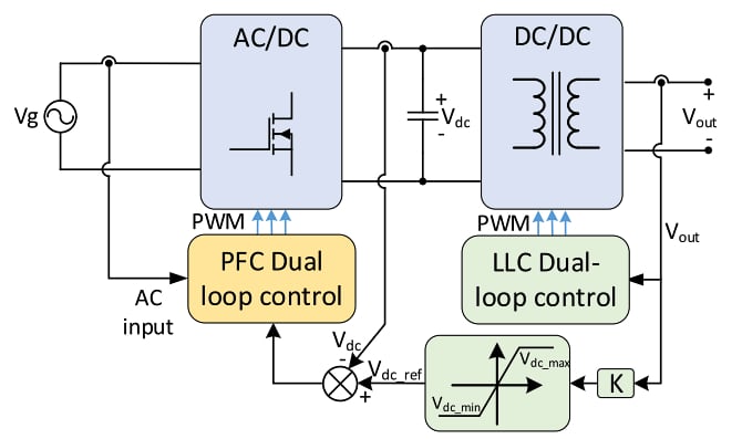
Figure 1. Block diagram of the linear feedback variable dc-link voltage control strategy of OBC. Image used courtesy of Bodo’s Power Systems [PDF]
Design Process of LLC Resonant Converter
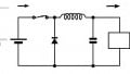
The topology of a full-bridge LLC resonant converter is shown in Figure 1. The primary side includes four power switches, i.e., Q1-4, and the second side comprises four diodes, D1-4. Note that the secondary side switches can be replaced with a synchronous rectifier to improve efficiency further. A resonant inductor Lr, a resonant capacitor Cr, and magnetizing inductance of the transformer Lm form the resonant tank.
Most EVs on the market have battery packs that consist of 80–100 4-V Lithium-ion batteries connected in series to provide 320–400 V nominal voltage. Three parallel-connected 3.7 kW OBC cells can deliver 11 kW power for the EV battery. The maximum output current is assumed to be 12 A.
The efficiency of an LLC converter is relevant to the voltage gain, which is expressed as;
Gain = Vout NS / Vdc NP. An LLC converter reaches its peak at the unit gain and reduces while the gain is too high or too low because of increasing copper loss due to the larger resonant tank current and higher frequency. Only Vdc can be changed when the OBC is running via tuning the PFC control. Thus, variable dc-link voltage control using linear feedback is used as it enables the LLC to operate in the vicinity of the resonant frequency. The feedback coefficient K is equal to the turn ratio of the transformer. By changing Vdc, the operation of LLC can be manually assigned closer to the unit gain. A saturation block keeps Vdc_ref between 198 V - 470 V owing to safety and efficiency considerations.
Role of Resonant Tank in Converter Operation
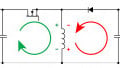
The resonant tank is a key component in the circuit as it helps convert the voltage from a battery bank into a form that can power electronic devices. It helps to regulate the output voltage by storing and releasing energy in a controlled manner. When the power switches in the circuit are turned on and off, the resonant tank helps smooth out the voltage waveform, reducing the amount of noise and distortion introduced into the system. This is important for maintaining the overall efficiency of the converter and reducing power losses.
Additionally, different hardware and software methodologies can be used to optimize the performance of the LLC converter’s resonant tank. These include adjusting the resonant inductance, employing modified circuit topologies or adaptive resonant tank parameters, and using improved modulation strategies or control schemes. But variable DC-link voltage control is one of the optimal software methodologies that adjusts the input dc voltage to assign the operation of the LLC converter closer to the resonant frequency, which is the peak efficiency point of the converter.
Experimental Analysis: Power Loss Model of LLC Converter
The design can be understood with analytical results of the power loss model of the LLC converter. Power loss can be classified into two dominant types: magnetic components and semiconductor loss.
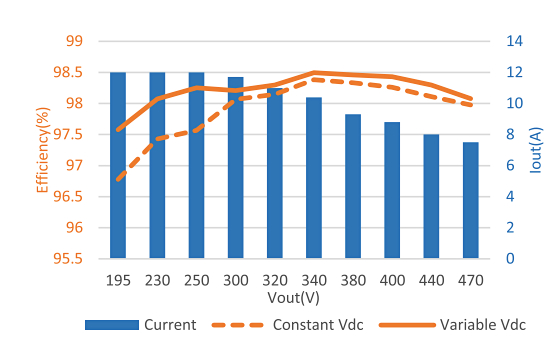
Figure 2. Simulation results: Comparison of efficiency with constant dc-link voltage control and variable dc-link voltage control. Image used courtesy of Bodo’s Power Systems [PDF]
The power loss model of each part is derived, and a simulation study is performed to validate the preliminary design. The magnetic component loss is evaluated with a third-order polynomial equation that fits the curve of Rac/Rdc versus frequency. The GaN HEMT loss is analyzed, and a DPT prototype is built to accurately characterize the switching loss of the device accurately. The power loss model of GaN HEMT is constructed with a second-order polynomial equation. The turn-ON energy loss of GaN HEMT is around a 100 μJ level, while the turn-OFF loss is lower than 10% of Eon. Hence, the study shows that the current design is more efficient than the conventional constant DC-link voltage control over the entire range of operation.
The experimental results also show that the variable dc-link control has a 0.8% higher peak power efficiency than the conventional control method. This means the current design is better at converting electrical power with less energy loss, which is important for applications where energy efficiency is critical.
Featured image used courtesy of Adobe Stock
This article originally appeared in Bodo’s Power Systems [PDF] magazine.