Facebook
 Google
 GitHub
 Linkedin
DC/DC Converters: Devices for Converting to a Lower Voltage
DC/DC converters are used in a wide array of systems in our day to day lives. The main goal of these converters is to step up or step down the DC voltage based on the application at hand while providing voltage regulation.
The basic form of a linear step-down device can be implemented using a resistor as a potential divider along with a diode to help with voltage stabilization. However, this setup will lead to heat dissipation leading to significant energy loss. As power is a crucial criterion in various electronic designs, step-down or Buck regulators are widely employed. Read on to learn more about the basics of step-down converters and how they work.
Overview
Voltage drop can be accomplished by using several means. It is important to understand the application at hand for determining the component and precision needs. A simple resistor can also be utilized for achieving desired voltage drop. However, this leads to power loss and is not an option in applications involving any form of storage element as power consumption is a key aspect of it [1]. This demands the need for a slightly more sophisticated implementation of a power electronics device such as a regulator and the converter used for voltage step-down is termed a Buck converter. The circuit diagram of a step-down or buck converter is shown in Figure 1.

Figure 1. Circuit diagram of a Buck converter. Image property of EETech
Buck converter aids in converting high voltage to low voltage very efficiently. This feature of efficient power conversion facilitates better battery life, reduced heat emission, and the ability to build compact devices. Also, step-down converters are known to offer a great balance of flexibility and usage due to the presence of an integrated controller and external inductor. Buck converter is a form of DC/DC converter that can accept input from either a DC source like a battery or from a derived source like AC mains via rectifier or reservoir capacitor circuit. The AC that is inputted to the initial rectifier stage could be a high voltage from the mains supply or lower voltage via a step-down transformer although in general high-frequency AC wave can be reconverted to DC more efficiently [2]. This flexibility enables the use of the step-down converter in numerous applications. Some of the applications of a step-down converter include computers, audio amplifiers, power inverters, motor controllers, battery and solar chargers.
High-level Operating Principle
A Buck converter is used to step-down a DC voltage from the input to the output [3]. The operation of the circuit is dictated by the conduction state of the switch. The switching transistor is placed between the input and output side and typically switches on and off continuously at high frequency. In order to effectively maintain the continuity of output, energy is stored in the inductor during the ON period of the switch, and the same is utilized during the OFF period of the switch.
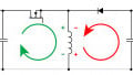
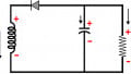
In on-state, the current through the inductor increases and the diode turns off blocking the path for current flow [4]. This is illustrated in Figure 2. During the off-state operation, the diode conducts the current because the current through the inductor cannot change abruptly. This leads to the transfer of energy from the inductor to the capacitor and is illustrated in Figure 3.
During the steady-state operation of the circuit, two modes of operation can be defined based on the inductor current value. If the inductor current never reaches zero, it is termed a continuous conduction mode. However, if the inductor current reaches zero, then it is said to be operating in discontinuous mode.

Figure 2. On-state operation of Buck converter. Image property of EETech

Figure 3. Off-state operation of Buck converter. Image property of EETech
The relationship between the input voltage and output voltage can be represented by means of the DC transfer function. For a step-down converter, the output voltage is defined by the product of input voltage and duty cycle. The duty cycle is defined as the percentage of the time the switch is turned on. In simple terms, the inductor and capacitor combination forms a low pass filter that smooths out the switching action while producing a clean DC voltage as a result.
Based on the DC transfer function, it can be inferred that as the duty cycle approaches zero, the output voltage also attains a zero value. Similarly, when the duty cycle approaches one, the voltage at the output side will be equal to the voltage at the input side.
Key Takeaways
- Buck converter is used to step down a DC voltage from the input to the output.
- For a step-down converter, the output voltage is defined by the product of input voltage and duty cycle.
- The inductor and capacitor combination forms a low pass filter that smooths out the switching action while producing a clean DC voltage as a result.
Key References
- Ned Mohan, Tore M.Undeland and William P.Robbins, Power Electronics: Converters, Applications, and Design, 3rd edition
- Robert W Erickson and Dragan Maksimovic, Fundamentals of power electronics, Springer Science & Business Media, 2007
- Rudolf P. Severns and Gordon E.Bloom, Modern DC-to-DC switch-mode power converter circuits, 1985