Facebook
 Google
 GitHub
 Linkedin
DC/DC Converters: Advanced Converter Topologies
Read on for valuable insight into advanced converter topologies, their classification, and how they work.
Switch-mode power converters have been used extensively in modern electronics technology across multiple sectors, including industrial, commercial, utility and consumer markets. For low-power DC/DC conversion-based applications, most modern power conversion is accomplished using three major types of power converters – buck, boost, and buck-boost. However, specialized applications require more advanced combinations or enhanced variations of the conventional topologies.
Advanced Converter Topologies
DC/DC converters form a key aspect of studying power electronics and energy drives as they are widely incorporated in several industrial applications. The DC/DC conversion technique was established in the 1920s [1]. Since then, DC/DC conversion techniques have advanced significantly. They are also undergoing significant changes due to two major industry trends: low voltage and high power density. This has led to the fact that the production of DC/DC converters worldwide is far beyond that of the AC/DC converters.
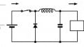
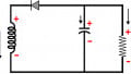
The simplest form of the DC/DC converter is a voltage divider like a rheostat or potentiometer. However, it can only transfer output voltage lower than the input voltage and also suffers from poor conversion efficiency. Some basic voltage divider circuits are shown in Figure 1.
The next step in the evolution of DC/DC converters is a multiple-quadrant chopper.
The growth in communication technology prompted the rapid development of DC/DC conversion techniques. At a high level, the DC/DC converters have been grouped into generations of DC/DC conversion topologies based on their evolution. They are categorized as belonging to different converter families. According to some statistics that are probably incomplete, more than 500 prototypes of the DC/DC converters have been developed in the past six decades.

Figure 1. Basic voltage divider circuits. Image property of EETech
Classification of DC/DC Converters
The classical or traditional converters are categorized as first-generation converters. They typically work in a single quadrant mode and operate in a low power range. These include fundamental converters like buck, boost, and buck-boost, and a few transformer-type converters.
Second-generation converters include multi-quadrant DC/DC converters, which work in two-quadrant or four-quadrant operation mode. They work in medium output power range and can be distinguished into two major categories – topologies derived from fundamental first generation converters and transformer-based topologies.
Third-generation converters are formed based on switched component converters and are implemented using either inductors or capacitors, thus called switched-inductor or switched-capacitor circuits. They perform in two or four-quadrant operations with a high output power range and have the advantages of high power density and conversion efficiency.
Fourth-generation converters are mainly composed of soft-switching converters like Zero Current Switching (ZCS) and Zero Voltage Switching (ZVS) converters. They can be categorized as resonant-switch converters, load-resonant converters, resonant-dc-link converters, and high-frequency-link integral-half-cycle converters. Most of the attention is focused only on the resonant-switch conversion method.
Fifth-generation converters include Synchronous Rectifier (SR) converters, which are instrumental in developing computing technology. In general, power supplies with low output voltage and strong current are widely used in communications, industrial applications, and computer equipment.
Sixth-generation converters are formed by multiple energy-storage elements resonant (MER) converters. These, in turn, have been categorized based on the resonant energy storage elements.
A summary of the family of DC/DC converters is illustrated in Figure 2.

Figure 2. Family of DC-DC converters. Image property of EETech
High-level DC/DC Converter Operating Principle
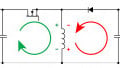
In the case of buck, boost, and buck-boost converters, the switch and diode are alternately on and off. They usually operate in continuous conduction mode and the inductor current is continuous. Some buck-boost converters like the SEPIC and Cuk build on the conventional topology while offering additional benefits like reduced current ripple at the terminals [2]. There are other transformer-based topologies like a forward converter, a flyback converter, push-pull converter, bridge converters, and Zeta converters [3]. These can be analyzed similarly to the fundamental converters and basic electrical principles of resonance and mutual inductance using circuit analysis concepts like Kirchoff’s laws.
Key Take-aways
- The simplest form of the DC/DC converter is a voltage divider like a rheostat or potentiometer. However, it can only transfer output voltage lower than the input voltage.
- The next step in the evolution of DC/DC converters is a multiple-quadrant chopper.
- At a high level, the DC/DC converters have been grouped into generations of DC/DC conversion topologies based on their evolution. They arere categorized such that they belong to different converter families.
Key References
1. Fang Lin Luo and Hong Ye, Advanced DC/DC Converters, CRC Press LLC, 2003
3. Rudolf P. Severns and Gordon E. Bloom, Modern DC-to-DC switch-mode power converter circuits, 1985