Facebook
 Google
 GitHub
 Linkedin
DC/DC Converters: Devices for Converting to a Higher Voltage
A DC/DC step-up or boost converter is one of the simplest switch-mode converter types, increasing the input voltage based on a given scenario.
DC/DC converters are used in several appliances used in our everyday lives. The main goal of these converters is to step up or step down the DC voltage based on the application at hand while providing voltage regulation.
A step-up or boost converter is one of the simplest switch-mode converter types, increasing or boosting the input voltage based on the requirements. There are ample scenarios where there is a need for a slightly higher voltage. Read on to learn more about the basics of step-up converters and how they work.
Boost Converter Basics
The history of the boost converter dates back to the 1960s and was initially used to power the electronic systems on an aircraft [1]. The initial requirements demanded that these converters be as compact and efficient as possible. This emphasized the need for the design to be simple and optimum. A step-up converter consists of an inductor, a semiconductor switch, a diode, and a capacitor [2]. It requires fewer parts for implementation and is less complicated than an AC transformer. The circuit diagram of a boost or step-up converter is shown in Figure 1.
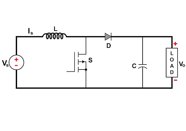
Figure 1. Circuit diagram of a boost or step-up converter. Image property of EETech
The main advantage of using a boost converter is its high efficiency. If well-designed, up to 99% of the input energy can be converted to useful output energy making the overall efficiency 99%. It is important to note that the design of a boost converter is mostly a compromise between the breakdown voltage of the switch (usually a MOSFET) and the on-resistance value. This is because the switch voltage needs to be rated for a high voltage as it sees voltage that is a summation of the supply voltage and the inductor voltage, which implies a high on-resistance.
It is also crucial to choose an inductor that withstands high currents and has a highly permeable core. This helps attain a high inductance value without compromising the overall design's compactness. The inductor is always connected on the input side and is a source of constant input current. This makes the boost converter a constant current input source where the load can be seen as a constant voltage source.
High-level Circuit Operating Principle
A boost converter or step-up converter aids in stepping up a DC voltage from the input to the output. The conduction state of the switch dictates the operation of the circuit.
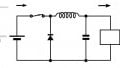
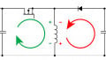
During the on-state, the current flowing through the inductor increases linearly. The diode is not conducting. This is shown in Figure 2. During the off-state, the diode conducts the current, and the energy transfer occurs from the inductor to the capacitor. This leads to a reduction of inductor current, although the current through the inductor cannot change abruptly [4]. This is illustrated in Figure 3.

Figure 2. On-state operation of a boost converter. Image property of EETech
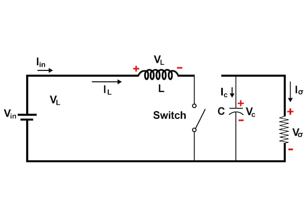
Figure 3. Off-state operation of a boost converter. Image property of EETech
Two important aspects to remember during the analysis of a boost converter include that the inductor current is continuous, which is possible only by choosing the correct inductance value. Also, the net change in inductor current over any complete cycle is zero because the inductor current value rises from a value with a positive slope to a maximum value during the on state and then drops back to the initial value with a negative slope [3].
During the steady-state operation of the circuit, two modes of operation can be defined based on the inductor current value. If the inductor current never reaches zero, it is termed a continuous conduction mode. However, if the inductor current reaches zero, it operates in discontinuous mode.
The following equation represents the relationship between the input voltage and output voltage:
\[V_{out}=V_{in}/(1-D)\]
where D is the duty cycle [5].
The duty cycle is defined as the percentage of the time the switch is turned on. In other words, the parallel combination of inductor and capacitor forms a second-order low-pass filter that smooths out the switching action while producing a clean DC voltage by reducing the voltage ripple.
Based on the relationship between the step-up converter's input and output voltage, it can be inferred that as the duty cycle approaches zero, the output voltage equals the input voltage. Similarly, when the duty cycle approaches one, the voltage at the output side grows infinitely.
Key Take-aways
- The boost converter is used to step up a DC voltage from the input to the output.
- The main advantage of using a boost converter is its high efficiency.
- The relationship between the input voltage and output voltage for a step-up converter can be represented as \(V_{out}=V_{in}/(1-D)\).
Key References
1. What is Boost Converter? Basics, Working, Operation & Design of DC Boost Converters
3. Boost Converter | Step Up Chopper
5. Rudolf P. Severns and Gordon E.Bloom, Modern DC-to-DC switch-mode power converter circuits, 1985