Facebook
 Google
 GitHub
 Linkedin
Understanding Attenuation in Signal Transmission
Attenuation is the loss of signal strength of an electrical or networking system while in transmission. In this article, you will learn how to define attenuation, type, measure, calculate and understand attenuation in fiber optic cables and networking.
Electrical and electronic gadgets involve networking cables. Networking cables are faced with the loss of signal strength challenge while the signal moves from the source point to the consumption end. It is good to note that this loss of signal strength does not change the content of the signal, but the intensity of the signal being transferred from one point to the other will be reduced. The process of signal strength loss is what is known as attenuation.
Defining Attenuation
Attenuation is defined as the loss of electrical parameters of an electronic wave or signal, for example, power, voltage, and current, during the process of transmission. The attenuation amount is given as a ratio of the output and input parameters under particular conditions.
One of the main reasons that trigger attenuation is the impedance within the transmission lines. The greater the impedance, the higher the attenuation.
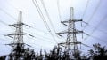
![]()
Figure 1. Attenuation. Image used courtesy of Simon Mugo
Measuring Attenuation
Attenuation is measured in decibels (dB) which is a tenth of the Bel that was a development of the Bell Telephone engineers. A decibel is defined as a logarithmic unit that explains how two measurements relate.
The equation below shows the disparity in decibels between two elements.
\[\nabla X (dB)=10log(\frac{X_{2}}{X_{1}})\]
Where
\(\nabla X\)=Disparity in measurement
X2 and X1 = Two dissimilar measured values of distance X
The formula logarithm is of base 10.
Types of Attenuation
In the area of electrical and networking, there are three classifications of types of attenuation: automatic, deliberate, and environmental.
Automatic Attenuation. This is mainly a feature in TVs and audio devices that avoid sound signal distortion by automatically sensing levels that are good for activating circuits.
Deliberate Attenuation. This one is done deliberately when sound is required to be adjusted in an electronic device to control volume to the required levels.
Environmental Attenuation. This is a result of signal power loss due to transmission channels such as fiber optic, copper wire, or wireless channels.
Measuring Attenuation
It is important to measure attenuation accurately, especially when the focus is on high-frequency RF applications and microwave communications. For instance, a designer of a radar system design can carry out an estimation of the amount of electric power a power transmitter can supply to the antenna when he has the right attenuation measurement.
Several methods exist for measuring the attenuation of a given communication system.
Power Ratio Method
For the power ratio method, the attenuation formula is determined by
\[A_{p}=10log_{10}(\frac{P_{IN}}{P_{OUT}})\]
Where
Ap = Power Attenuation
PIN = Input Power
POUT = Output Power of the Transmission Line
The formula can be written by considering power at the transmitter end or power at the source. The power at the receiver, or destination power, is shown below:
\[A_{p}=10log_{10}(\frac{P_{T}}{P_{R}})\]
Or
\[A_{p}=10log_{10}(\frac{P_{S}}{P_{D}})\]
Where
PT = signal power at the transmitter
PR = Signal power at the receiver
PS = Source power
PD = Destination power
Voltage Ratio Method
Besides power, input and output voltages can be involved in the determination of attenuation.
The formulas below can be used in this case
\[A_{V}=10log_{10}{\Bigg(}\frac{V_{IN}}{V_{OUT}}{\Bigg)}\]
Or
\[A_{V}=10log_{10}{\Bigg(}\frac{V_{S}}{V_{D}}{\Bigg)}\]
Or
\[A_{V}=10log_{10}{\Bigg(}\frac{V_{T}}{V_{R}}{\Bigg)}\]
Where
AV = Voltage attenuation
VIN = Input voltage
VOUT = Output voltage
VT = Transmitter Voltage
VR = Receiver voltage
VS = Source voltage
VD = Destination voltage
Attenuation vs. Amplification
Attenuation involves signal strength loss. Amplification is the opposite of attenuation in that it involves signal gain. Therefore, amplification is the corrective measure for attenuation.
For example, when tuning the radio by adjusting the volume knob, the process is amplification not attenuation.
The best way to minimize attenuation in television cables is by using a repeater which is a device made of an amplifier circuit to boost slightly weak TV signals.
Attenuation in Optical Fiber
Optical power is lost when light is transmitted through the fiber optic. These losses are classified as attenuation and are caused by factors such as scattering, absorption, and losses due to bending.
Here, the optical fiber signal attenuation is the ratio of input optical power to the optical output power expressed as
\[A_{Optical-fiber}=10log_{10}{\Bigg(}\frac{P_{I}}{P_{O}}{\Bigg)}\]
Where
AOptical-fiber = optical fiber attenuation
PI = optical input power
PO = optical output power
The following factors can cause attenuation in optical fiber.
Absorption loss. This loss is due to the optical fiber fabrication method and the material used. It can cause the dissipation of power of the cable. Besides glass fiber being so clean, some deposits of contamination remain even after they undergo cleaning. The contaminants cause power dissipation through absorption.
Micro bend Loss. While fiber exists, tiny microscopic bends occur. The tiny bends are sometimes caused by external forces, irregular coating, and improper cabling of the fiber optics. The bends scatter away optic signals hence inducing attenuation.
Scattering Loss. This can be triggered by fluctuations in the light density in the cable of optical fiber.
Attenuation in Networking
Communication signal losses in the computer network are also computed in decibels. With attenuation on communication, even transmission of an email through the network becomes distorted.
The following are reasons attenuation occurs in networking.
Range. Transmission is slowly dispersed over longer distances in both wired and wireless systems.
Wire size. On wired systems, thick wires experience less attenuation than thinner wires.
Interference. Interferences such as radio on wireless networks cause attenuation.
Problem
Suppose a radio transmitter signal travels through the transmission cable medium, and its signal power is downgraded to one-fourth, calculate the attenuation of the signal.
Solution
The attenuation can be calculated using the formula below
\[A_{P}=10log_{10}{\Bigg(}\frac{P_{IN}}{P_{OUT}}{\Bigg)}\]
Where
Ap = Power Attenuation
PIN = Input Power
POUT = Output Power of the Transmission Line=\(\frac{P_{IN}}{4}\)
Replacing values in the formula
\[A_{P}=10log_{10}(\frac{P_{IN}}{4P_{IN}})\]
\[A_{P}=10log_{10}{\Bigg(}\frac{1}{4}{\Bigg)}=-6dB\]
The attenuation is -6dB.
A negative dB value explains attenuation/loss while a positive dB value explains amplification/gain.
Key Takeaways of Attenuation
- Attenuation is the loss of electrical signals during transmission
- Attenuation is measured in decibels
- Attenuation is corrected by amplification of the signals
- When a decibel change in signal is negative, that is attenuation, while if the decibel change is positive, the signal is amplified.
- Three types of attenuation exist: deliberate, environmental, and automatic attenuations.
- Attenuation can be calculated based on several parameters, such as power and voltage.
Featured image used courtesy of Adobe Stock