Facebook
 Google
 GitHub
 Linkedin
Five Ways to Reduce Harmonics in Circuits and Power Distribution Systems
There are several ways to reduce the problems of harmonics in a circuit or power distribution system. A K-rated transformer is designed to withstand the overheating problems created by harmonics. A harmonic mitigating transformer is designed to reduce problems by reducing or canceling harmonics. In addition, harmonic filters are occasionally used to reduce harmonics.
K-Rated Transformers
ANSI Standard C57.110-1986 defined a K-factor to evaluate how much harmonic current a circuit draws and to determine the heating effect of that harmonic current. Based on the circuit K-factor, transformers are manufactured with a K-rating. It is important to note that K-rated transformers do not reduce harmonics. The K-rating indicates the relative ability of a transformer to withstand the harmful effects of harmonics. K-rated transformers increase the size of the core, increase the size of the neutral conductor, and use special winding techniques to reduce eddy current and skin effect losses. For example, we know that doubling the cross-sectional area of a conductor reduces its resistance by half. A K-rated transformer uses heavier gauge wires for the primary and secondary coils to reduce the resistance heating.
Note:
The occurrence of sags and swells may indicate a weak power distribution system. In such a system, the voltage will change dramatically when a large motor or welding machine is switched on or off.
Measuring K-Factor
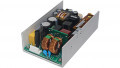
In any system containing harmonics, the K-factor can be measured with a power quality analyzer (see Figure 1). A K-factor of 1 indicates a linear load. A higher K-factor indicates increased heating from harmonics. For example, a circuit with a K-factor of 2 has twice the heating effect of a circuit with a K-factor of 1.

Figure 1. The K-factor can be measured with a power analyzer. Image Courtesy of Mouser
Standard K-ratings are 1, 4, 9, 13, and 20. In addition, K-ratings of 30, 40, and 50 exist, but loads with K-factors greater than 20 are relatively rare. Computer rooms typically have K-factors of 4 to 9. Areas with many single-phase computers have K-factors of 13 to 17. The K-rating of the transformer should exceed the K-factor of the circuit, or the transformer should be derated.
Circuit Load
Guidelines have been developed that recommend a K-factor based on the predominant type of load in a circuit (see Table 1). When specifying a transformer based on the K-factor, more is not better. A transformer with a K-factor greater than needed has its own set of problems. Typical problems include increased inrush current, higher eddy current core losses, and a larger footprint.
|
Predominant Load |
K-Factor |
|
Incandescent lighting Resistance heating Motors without solid-state drives Control Transformers/ Electromagnetic Control Devices |
K-1 |
|
UPS without input filtering Welders Solid-state controls other than variable-speed drives |
K-4 |
|
UPS without input filtering Multiwire receptacle in classrooms and general care areas of health care facilities |
K-13 |
|
Mainframe computer loads Variable-speed motor drives Multiwire receptacle circuits in critical care areas of health care facilities |
K-20 |
|
Other loads producing large amounts of harmonics |
K-30, K-40, K-50 |
Table 1. The K-factor of common loads can be estimated.
The K-factor of a circuit generally decreases with more loads connected to the circuit, just as the THD decreases with more identical loads on a circuit. Typically, with 10 or 20 devices simultaneously online, the combined K-factor at the bus of the distribution panel is reduced by a factor of 3 or more.
Harmonic Mitigating Transformers
A harmonic mitigating transformer (HMT) is a transformer designed to reduce the harmonics in a power distribution system. Some styles of HMTs are referred to as phase-shifting transformers. HMTs generally work on the principle of combining the waveforms in ways where the positive part of a harmonic component from one load adds to the negative part of a harmonic from another load. This addition results in complete cancellation when the loads are perfectly balanced. With unbalanced loads, we’ll still be able to have a much smaller overall harmonic. The end result is that harmonics are prevented from propagating through the power distribution system, but they remain in the secondary windings and the load side of the system.
An HMT works best when located close to the load. This generally means that HMTs are located at scattered locations throughout a facility. Therefore, HMTs are usually available with kVA ratings of about 100 kVA or less.
Delta-Wye Wiring
A common transformer wiring arrangement has the primary wound in a delta configuration with the secondary wound in a wye configuration. Delta-wye transformers have a higher impedance to the flow of harmonic currents than to the fundamental current. This reduces the current harmonics, but higher impedance in the transformer causes a relatively higher voltage drop from the harmonic currents. The high voltage drop contributes to voltage THD and flat-topping. This voltage THD can be distributed up-stream throughout the power distribution system. At full load, a delta-wye transformer can produce voltage THD above that recommended by the IEEE Standard 519-1992, IEEE Recommended Practices and Requirements for Harmonic Control in Electrical Power Systems.
While the triplen harmonics are attenuated, the other higher-order harmonics are not affected. However, if an HMT is being used to provide additional source impedance and/or phase shift from other nonlinear loads elsewhere in the facility, some benefits may be achieved.
Zigzag Windings
Another common HMT design is to wind the secondary of each phase in a zigzag configuration to eliminate the triplen harmonics. The zigzag is achieved by winding half of the secondary turns of one phase of the transformer on one leg of the three-phase transformer, with the other half of the secondary turns on an adjacent phase (see Figure 3).

Figure 3. A zigzag winding is used to cancel triplen harmonics.
When all of the triplen harmonics are in phase with each other, the triplen harmonic currents generate ampere-turn fluxes that offset each other, causing no currents to be induced in the primary winding.