Understanding Power Modules in Embedded Drives
While embedded motor drives are gaining popularity in industrial applications, their compact size and tight integration present new challenges in terms of heat dissipation and electromagnetic interference. This article outlines these challenges and presents how they can be overcome using Vincotech thickfilm technology.
Motor drive applications are considered state-of-the-art in many industrial businesses. Most standard induction motors operate from fixed-frequency sinusoidal power. These days, however, motors with adjustable or variable frequency drives (VFDs) are gaining popularity. These can be broken down into two categories. The first, decentralized drives, use an external inverter mounted, for example, on the motor connection box. Embedded drives, on the other hand, use an internal inverter that is part of the motor itself and can sometimes not even be seen from outside.
The main design constraints for embedded drives used, for example, in non-industrial fans and pumps, are space availability and the reduction of motor and inverter losses. In addition, they need to fulfill power factor requirements.
Environmental Conditions
Moving the inverter from the control cabinet to the motor has led to new inverter design requirements. Among the most demanding is thermal management. Standard cabinet-mounted inverters operate in a rather friendly environment with no particular IP protection requirements, unlike the motor, which is installed somewhere in the production line near the goods that are being processed. By contrast, embedded drives use an internal inverter, which requires both the motor and the inverter to be water- and dustproof, impacting the system’s thermal properties.
In IP65-protected systems, the dissipated power of all components can only exit through their surface, mainly via the heatsink. Inverters used in embedded systems must, therefore, be designed to minimize power dissipation and to connect all their power-dissipating components to the heat sink using a good thermal interface. Keeping the overall temperature low and avoiding hot spots inside the system ensures overall system reliability.

Figure 1. CI + PFC topology. Image used courtesy of Bodo’s Power Systems [PDF]
In addition, inverters have to be small enough to fit into a given environment to enable a compact motor design and high installation density. Examples can be found in water treatment, heat pumps, and ventilation systems. The reduction of the system’s surface area makes optimized thermal management even more important. At the same time, shrinking overall system volume requires an intelligent system split that minimizes interconnections between the power section, the energy storage, and the inverter’s control board.
Common requirements across all applications are rectifier diodes, a passive or active PFC, and an inverter stage for the motor, as shown in Figure 1. An additional PFC circuit is required to fulfill the Energy Efficiency Directive, established in 2012, to develop applications with higher efficiency.
Figure 2 shows two well-known applications of embedded drives that illustrate the compactness enabled by integrated inverters.

Figure 2. A Wilo pump and an ebm-papst fan as examples of embedded drive systems. Image used courtesy of Bodo’s Power Systems [PDF]
The challenge lies in moving components with creepage and clearance requirements – that need a lot of space on the PCB – to new locations where other rules apply. These components include the CI + PFC semiconductors as well as parts for the boot-strap circuit, shunts, snubber capacitors, etc. And this is where the power module comes into play. Power modules are usually filled with an electrically isolating silicone gel with a dielectric strength of several kilovolts per millimeter. Covering components with silicone makes it possible to pack them more densely.
One obstacle is the minimum distance between two tracks, which needs to be >0.5 mm when a standard Al2O3 DCB is used. This is less of an issue for bare dies of power semiconductors but becomes more challenging for discrete components such as resistors, capacitors, and diodes, and even more so for ICs. In these cases, Vincotech’s thick film technology offers the most promising solutions, with achievable fine pitch distances of less than 0.5 mm.
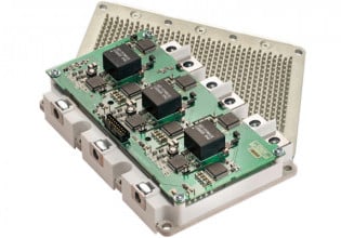
Vincotech offers two types of modules for embedded drive applications: DCB modules that only include power semiconductors and thick film modules that also include active and passive components. While both are based on aluminum oxide, their main differences are the base material thickness and whether they have copper planes on either side. Because Al2O3 is a fragile material and needs to be handled with care, thick film substrates are about twice as thick as DCBs, at about 1 mm. Additionally, they have a higher thermal resistance because the absence of the top and bottom copper does not allow thermal spreading.
Thick-film modules are based on a technology that allows printing different layers on an aluminum oxide substrate, which is then fired at 850 °C. A variety of pastes are available for different purposes, such as low ohmic conductors for high-power tracks and resistor pastes ranging from low values for shunts to high values in the MΩ range for all kinds of resistor functions.
Laser trimming the resistors increases their accuracy, and adding a glass passivation layer improves their reliability.

Figure 3. Comparing a DCB-based module (left) and a thick film module (right). Image used courtesy of Bodo’s Power Systems [PDF]
The schematic below depicts the components that are integrated into the thick film module. First, unlike in the case of standard power modules, the gate driver IC is implemented, including diodes, resistors, and–this is very rare–capacitors. Finally, it shows a gate resistor and a gate-emitter capacitance as an example. Other Vincotech thick film products have different turn-on and turn-off gate resistors and, optionally, a gate-emitter resistance to discharge the gate in the absence of a power supply.

Figure 4. Internal circuit of a thick film power module. Image used courtesy of Bodo’s Power Systems [PDF]

Figure 5. EMI measurement without Cge (left) and with integrated Cge (right). Image used courtesy of Bodo’s Power Systems [PDF]
The circuit also includes a PFC circuit with a fast 650 V IGBT or an even faster Si MOSFET as well as a fast Si diode or, when even higher switching frequencies and efficiencies are required, a SiC diode.
A ceramic capacitor between DC+ and DC- closes the high-frequency loop inside the power circuit. Capacitors between the gate and the emitter further improve EMI, as shown in Figure 5.
Capacitor placement can strongly impact measured values.
Takeaways of Power Modules in Embedded Drives
Two different types of power modules are widely used in embedded drive applications: DCB modules that only include power semiconductors like a PFC stage and the inverter stage and highly integrated modules based on thick film technology. Vincotech IPMs based on thick film technology make it possible to add passive components where they are needed: as close as possible to the power semiconductors. Components such as the complete bootstrap circuit, which includes capacitors and shunt resistors, offer engineers clear benefits in terms of size. Moreover, they can design PCBs without having to add additional creepage and clearance distances, making it possible to further shrink their applications. The outstanding electrical properties of other components, such as the X2 and gate emitter capacitors, make it possible to reduce the size of some of the filters on the PCB and, in some cases, even make them obsolete.
This article originally appeared in Bodo’s Power Systems [PDF] magazine


