Facebook
 Google
 GitHub
 Linkedin
Substation Design and Layout Planning—Part 2: Safety and Thermal Controls
This article explains how a substation’s physical layout must integrate safety clearances, grounding, and thermal management.
Designing a substation that is both safe and resilient requires translating abstract requirements from codes and standards into tangible spatial decisions. Two areas that most strongly influence layout are safety clearances with human‑factor considerations and thermal/environmental controls that preserve equipment life and performance. The aim is to connect the “what” prescribed by standards with the “how” of placing equipment, routing people, and managing heat and environment.
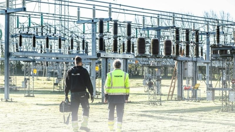
Substation workers. Image used courtesy of Pexels
Safety Clearances and Human‑Factor Design
Electrical clearances govern nearly every physical layout decision. For air‑insulated yards, phase‑to‑phase and phase‑to‑ground distances should be selected using a consistent insulation‑coordination basis and then mapped directly into the plan view and elevation drawings.
IEEE Std 1427 provides recommended operating and safety clearances for 1 kV to 800 kV AIS, linked to Basic Insulation Level (BIL) and environmental factors. It also explains how reduced clearances can be justified when insulation coordination and arrester protection are properly engineered.
Clearance selection should also consider altitude and contamination, which alter withstand capability and may require increasing creepage and air gaps. In jurisdictions governed by the National Electrical Safety Code, the 2023 NESC serves as the primary reference for substation safety rules, including access control and guarding of live parts. Regions operating under IEC practice generally apply IEC 61936-1, which defines high-voltage installation layout principles and interfaces between equipment classes.
Gas‑insulated substations (GIS) have internal dielectric design handled by the manufacturer, but the external safety envelope and access provisions still follow site codes and the project’s clearance criteria.
Clearances
OSHA 29 CFR 1910.269 specifically requires sufficient access and working space around substation equipment for safe operation and maintenance, and mandates guarding or adequate clearances where energized parts exceed 150 V to ground.
For buildings and enclosed rooms, exit‑route rules from OSHA 1910.36 apply. Exit capacity may not decrease in the direction of travel, minimum heights and widths must be maintained, and routes must support the maximum occupant load.
Industrial facilities commonly align these arrangements with locally adopted NFPA 101 Life Safety Code requirements. In practice, this means aligning doors, aisles, and gate swings so an open panel or relay‑rack door never blocks an escape path, and placing entrances at opposite ends of working spaces serving large equipment.
Human‑Factor Design
Human‑factor design reduces error temptations. The substation’s physical design should guide people’s routine foot traffic outside electrical approach boundaries, reducing the likelihood of encroachment during energized work.
NFPA 70E defines shock protection boundaries (limited and restricted) and the arc‑flash boundary. Layout can reinforce these by using permanent barricade anchors, painted floor lines in control houses, and clear equipment labeling.
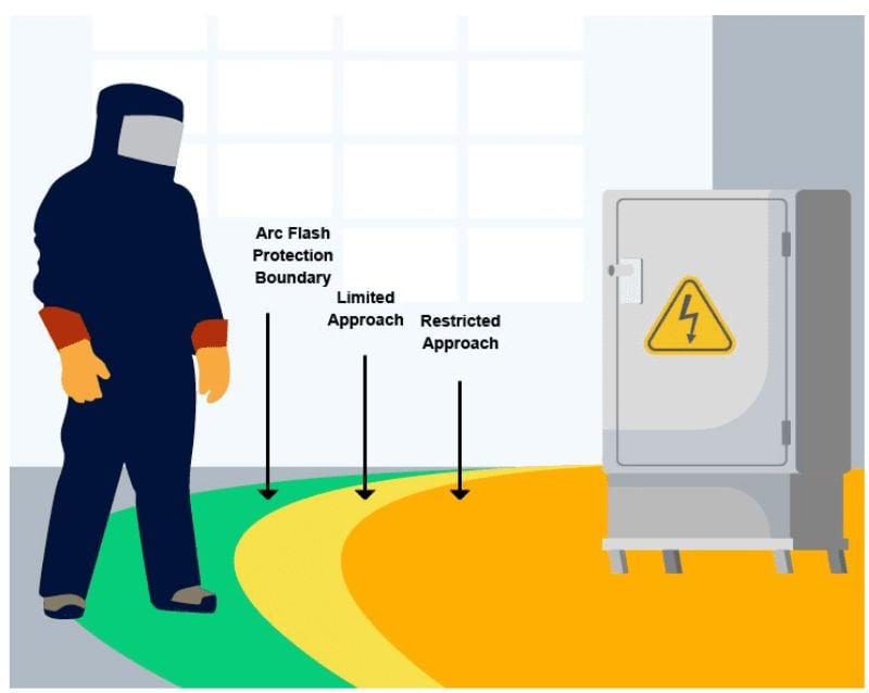
Figure 2. NFPA 70E, shock protection boundaries. Image used courtesy of Weifield Contracting
The latest NFPA 70E revision updated approach‑boundary alignment with OSHA minimum approach distances and added elevation notes that can affect clearance at high‑altitude sites, making site elevation a necessary input to clearance calculations.
Lockout/Tagout
The layout should facilitate LOTO by providing safe approach zones, well-positioned isolation devices, and unobstructed visibility for verifying equipment status before applying locks or tags.
OSHA 1910.147 requires a documented energy‑control program and hardware enabling positive isolation. Locating group LOTO stations near bay entrances, providing hasps and lock rails at isolation points, and ensuring tags remain visible from normal approach directions all shorten the path to an electrically safe work condition. Outdoor bays benefit from dedicated, level standing zones at disconnects and grounding switches to keep crews clear of wheel ruts and ice during switching or grounding.
_.jpg)
Figure 3. Lockout/Tagout (LOTO). Image used courtesy of Electrical Training Pro
Grounding
Grounding/earthing is integral to the physical layout, not only a calculation. IEEE Std 80 establishes step‑ and touch‑voltage safety criteria and the design approach for grids, while IEEE Std 81 provides measurement methods for soil resistivity and post‑installation verification—inputs which affect grid geometry, conductor spacing, and extension under travel paths.
High‑resistivity surface layers (crushed rock) reduce body current and allow higher permissible surface potentials for the same risk level. This design choice should extend under all normal walking routes, gates, and around operating handles.
For two‑layer soils or high perimeter currents, designs typically densify the outer meshes, add ground rods near major sources (transformer neutrals, breaker frames), and bond fences and gates to the grid so that no inadvertent potential differences appear along an evacuation path.
Thermal Management and Environmental Controls
Thermal performance begins with the transformer, which often drives substation spacing and airflow. IEEE C57.91 is the loading guide for mineral‑oil‑immersed transformers and step‑voltage regulators. It explains how ambient temperature, cooling class (ONAN/ONAF/OFAF/OFWF), and auxiliary losses combine to set winding and hot‑spot temperatures and, in turn, loss of life.
The guide’s Arrhenius‑based aging model shows how small hot‑spot increases sharply accelerate insulation aging. A widely used expression for the aging acceleration factor (FAA) relative to a 110°C reference is:
$$F_{AA} = e^{( \frac{15000}{383} - \frac{15000}{\theta_{HS}} )}$$
with ፀHS the winding hot‑spot in °C. Designers should situate transformers with unobstructed airflow paths, avoid recirculation by respecting wall and fire‑barrier stand‑offs, and align fans/radiators with prevailing winds where feasible. All these measures reduce thermal gradients and fan duty while preserving emergency loading headroom.
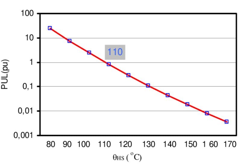
Figure 4. Transformer’s isolation loss of life. Image used courtesy of Najdenkoski et al.
Equipment Derating
Switchgear and bus equipment impose their own thermal limits, which directly influence building HVAC sizing and outdoor yard layout.
Medium‑voltage metal‑clad or metal‑enclosed switchgear is rated for a 40°C ambient. Above that, IEEE C37.20.2 requires derating to maintain allowable temperature rise at buses, connections, and cable compartments. Manufacturer application data based on that standard provides practical numbers. For example, a 1200 A continuous rating may reduce to roughly 980 A at 45°C and ~944 A at 50°C.
Outdoor enclosures exposed to solar radiation can experience an additional internal rise. IEEE C37.24 addresses evaluating solar radiation effects, showing that elevated solar heat gain reduces continuous current capability unless shading or ventilation is provided. Altitude also matters. Reduced air density degrades both cooling and dielectric withstand, prompting altitude correction factors for current and withstand ratings.
Control Buildings
Control buildings, though small in volume, are thermally sensitive environments that strongly influence the reliability of protection and control equipment. Protection relays, RTUs, and networking devices are best treated as industrial electronics rather than office loads.
IEEE 1613 defines environmental and EMC tolerances for devices with communications functions used with electric power apparatus. Selecting 1613‑qualified equipment and applying good cabinet airflow management reduce nuisance outages caused by temperature excursions and electromagnetic disturbances.
For room setpoints, ASHRAE TC 9.9’s recommended inlet range of roughly 18-27°C with dewpoint control provides a defensible target, recognizing that many substation IEDs tolerate wider ranges but that relay timing and clock stability are better at moderate temperatures.
SCADA and DC systems introduce additional environmental and ventilation requirements. Battery rooms and chargers need ventilation tailored to the chemistry. Control‑house HVAC should avoid placing return grilles directly over battery doors to prevent corrosive migration into electronics spaces.
Communications racks benefit from hot‑aisle/cold‑aisle orientation even at a small scale. Maintaining a generous aisle clearance prevents supply diffusers from being blocked by open doors during commissioning.
Where equipment is installed outdoors (RTU cabinets, marshalling boxes), specifying Class C environmental ratings per IEEE 1613 temperature classes, and shading those cabinets, can dramatically lower enclosure temperatures and the associated electronics failure rate.
Ambient Temperature
Ambient temperature is also a lifecycle variable, not just a one‑time rating check. Transformer aging models show that a 10°C increase in winding hot-spot temperature roughly triples insulation aging rate, reducing the life margin intended for emergency duty. Conversely, cool sites gain aging headroom that can be “spent” on short seasonal overloads.
The practical takeaway is to tie the thermal model to local weather files and altitude: define normal, long‑time emergency, and short‑time emergency ratings for the actual site rather than the nameplate default, and verify that cable and termination thermal limits remain coordinated with those ratings. Keeping thermal assumptions explicit in the one‑line and equipment schedules makes future uprating assessments faster and safer.
Safe Egress
Finally, thermal design must coexist with safe egress. HVAC units, radiators, and auxiliary skid placements should never pinch exit routes. OSHA exit‑route capacity and minimum dimensions apply to control buildings. Maintaining clear, non‑slip pathways with adequate lighting and no thermally induced hot surfaces within reach aligns thermal and human‑factor goals.
For outdoor yards, placing radiators and fan plenums outside normal foot traffic, and keeping hand‑operated devices in shaded, ventilated positions, improves both safety and maintainability.
Conclusion
Clearances and thermal controls translate directly into layout lines, equipment spacing, and the day‑to‑day experience of crews.
A robust substation plan selects electrical clearances using a traceable insulation‑coordination basis, reserves safe working and escape routes consistent with OSHA and life‑safety principles, and embeds LOTO and grounding safety into the physical arrangement. The plan then manages heat by applying transformer thermal models, derating switchgear and outdoor gear for solar heat gain and altitude, and conditioning control‑house environments to ASHRAE/IEEE expectations.
Treating these considerations as a single, integrated design framework—spanning spatial layout, human interaction, and thermal performance—yields substations that operate safely and maintain adequate performance margins throughout their service life.