Facebook
 Google
 GitHub
 Linkedin
Substation Components—Part 8: Grounding/Earthing Systems
As we wrap up this series, this article outlines the purpose of substation grounding, the IEE Std 80 design, and best-practice field testing.
Grounding (earthing) is the safety backbone of every substation. A properly engineered ground grid limits hazardous voltage gradients during faults, provides a low-impedance path so protective devices clear quickly, and establishes a common reference that reduces electromagnetic interference across control, protection, and communications systems.
This article examines the purpose of substation grounding, outlines the IEEE Std 80 design approach with emphasis on step and touch potential limits, discusses common grounding materials, and concludes with best‑practice field testing per IEEE Std 81.
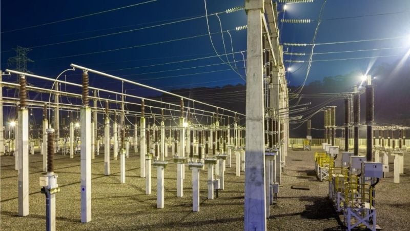
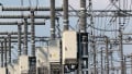
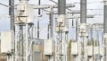
High-voltage substation. Image used courtesy of Adobe Stock
Why Grounding Matters
Personnel safety. Step and touch potentials arise when fault current flows into earth through a substation grid. Without an adequate grid, the voltage difference between two feet (step) or between a hand touching grounded metal and the ground underfoot (touch) can reach fibrillation thresholds.
OSHA emphasizes the hazard and the need to control voltage gradients around grounded objects, aligning with IEEE guidance.
Fault current dissipation and equipment protection. A dense, low-impedance grid spreads current over a large area and lowers ground potential gradients, helping protective devices operate within specified clearing times. Ground potential rise (GPR) at the substation rises roughly in proportion to fault current and the grid’s impedance to remote earth. Minimizing that impedance is a core design aim.
Electromagnetic compatibility (EMC). A well-bonded, meshed ground plane reduces common‑mode noise, controls transferred potentials to control cables and telecom circuits, and provides a consistent reference for surge protective devices. Where conductors exit the substation, isolation (for example, fiber instead of copper) prevents hazardous transferred voltages during faults.
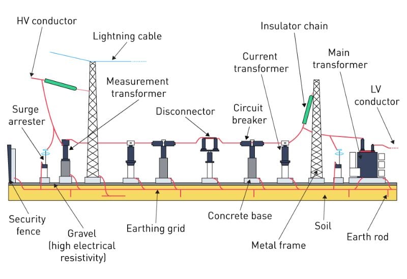
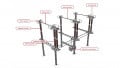
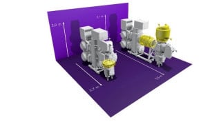
Figure 1. Substation grounding. Image used courtesy of Monolithic Power
Grid Design Fundamentals
IEEE Std 80 (Guide for Safety in AC Substation Grounding) defines a structured method to design grids that keep calculated step and touch voltages below tolerable limits for the site’s soil conditions and protective clearing time.
Although the standard contains detailed procedures, engineers generally follow this sequence:
1. Establish design inputs.
- Maximum single-line-to-ground fault current flowing to earth via the substation grid (accounting for current division with overhead shield wires, neutrals, and metallic return paths).
- Protective clearing time for the worst credible fault on the grounded system.
- Soil model (uniform or multilayer) derived from resistivity measurements.
- Site conditions affecting a surface layer (crushed rock, asphalt) and the fence line layout.
2. Lay out a preliminary grid. Typical practice is a rectangular mesh of bare conductors buried at approximately 0.3–0.5 m depth with 3-7 m spacing, augmented with perimeter conductors and ground rods at corners and around equipment. This geometry improves current dispersion and reduces voltage gradients; it is consistent with common guidance derived from IEEE 80.
3. Compute GPR and estimate grid impedance. Ground potential rise is the product of grid current and grid impedance to remote earth; it provides a useful upper bound for the surface voltage profile that will later be compared to step/touch limits.
$$GPR = I_f ~\times~Z_{grid}$$
4. Evaluate step and touch voltages. IEEE 80 defines methods to compute worst‑case mesh (touch) and step voltages considering geometry, burial depth, soil, and a surface‑layer derating factor Cs. The calculated values (Em and Es) must be less than the tolerable limits given by the standard’s criteria.
5. Iterate and mitigate. Reduce mesh spacing, add conductors and vertical rods (especially at the perimeter), and use higher‑resistivity surface cover (crushed rock) to lower actual step/touch voltages and raise allowable limits via the Cs factor. Where transferred potentials are possible (pipes, rails, cable sheaths, fences), address isolation or equipotential bonding per the standard.
Step and Touch Voltage Criteria
IEEE Std 80 provides explicit, tested equations for the tolerable step and touch voltages based on body mass and exposure time.
- General form:
- Step voltage limit: \(E_{step} = (R_B + 2 R_f) \times I_B\)
- Touch voltage limit: \(E_{touch} = (R_B + \frac{R_f}{2}) \times I_B\)
- Allowable body current: \(I_B = \frac{k}{\sqrt{t_s}}\), with k depending on body mass and ts the duration of shock current in seconds.
Where:
- RB = 1000 Ω is the standard total body resistance used for design.
- Rf is the “foot” resistance term; when expressed through the surface layer, it appears in the combined constants multiplying Cs × ρs.
- ρs is the resistivity of the surface layer (Ωm), such as crushed rock.
- Cs is the surface layer derating factor; it depends on the surface layer thickness, resistivity, and contact geometry.
- ts is the duration of shock current in seconds.
- k is 0.116 (50 kg) or 0.157 (70 kg).
- For a given soil cover, clearing time, and Cs, the calculated mesh (touch) and step voltages must fall below Etouch and Estep, respectively.
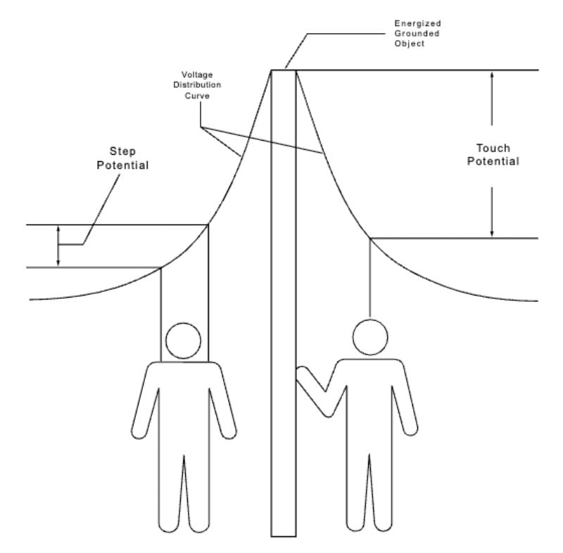
Figure 2. Step and touch potential. Image used courtesy of Cornell University
Permissible Ground Potential Rise (GPR)
GPR expresses the maximum voltage of the grid with respect to remote earth during a fault:
$$GPR = I_f \times Z_{grid} \approx I_f \times R_g$$
Where:
- If is the grid current to earth
- Zgrid (or Rg) is the grid impedance (resistance) to remote earth.
GPR itself is not an independent acceptance criterion in IEEE 80; rather, it provides a bound on the surface potential profile against which the computed mesh and step voltages are compared to the tolerable Etouch and Estep. In practice, permissible GPR is the value that satisfies the acceptance conditions:
- Em(calculated mesh/touch) ≤ Etouch(limit), and
- Es (calculated step) ≤ Estep(limit), for the chosen body mass model and ts.
If computed Em or Es exceeds the limit, lowering Rg (more conductors/rods, larger grid area), reducing If (system changes), reducing ts (faster clearing), or increasing Cs × ρs (thicker/higher‑resistivity surface layer) will reduce GPR, increase tolerable limits, or both.
Typical Grounding Materials
Conductors. Bare copper is widely used for its low resistivity, ease of exothermic welding, and corrosion performance in many soils. In cost‑sensitive or corrosion‑managed applications, galvanized steel (zinc‑coated) is also common for grid conductors, counterpoises, or structures. Material selection weighs conductivity, mechanical durability, soil chemistry, and galvanic compatibility with connected structures.
Connections. Exothermic welds provide low‑impedance, mechanically robust, corrosion‑resistant bonds between conductors and to equipment pads. Mechanical clamps and compression connectors are used where welding is impractical, but these require inspection and corrosion mitigation.
Vertical electrodes. Driven rods (copper‑bonded steel or galvanized steel), deep wells, and structure foundations (Ufer grounds) are used to reach lower‑resistivity layers and to reduce Rg. Rods are particularly effective around the perimeter to steepen the decay of surface potentials near fence lines.
Surface layer. A layer of crushed rock or asphalt increases ρs and, through Cs × ρs, increases tolerable step and touch voltages for the same body‑current limit. The surface layer also reduces current density at the surface, providing a second layer of protection during faults.
Fence and gate bonding. IEEE 80 provides detailed guidance on fence grounding and gate bonding to avoid hazardous gradients where people might stand, including special attention to perimeter conductors, gate jumpers, and interfaces with adjacent property or public walkways.
Ground Resistance Testing and Soil Resistivity Surveys
IEEE Std 81 defines best‑practice methods for soil resistivity surveys and for verifying existing grounding systems.
Soil Resistivity Surveys
- Wenner four‑pin method. Four equally spaced probes are driven in a straight line at spacing a and depth b. Inject current through the outer probes and measure voltage between the inner probes to obtain resistance R; the apparent resistivity is computed from:
$$\rho_a = \frac{4 \pi a R}{1~+~\frac{2a}{\sqrt{a^2~+~4b^2}}~-~\frac{a}{\sqrt{a^2~+~b^2}} }$$
For shallow probe depth (b ≪ a), this simplifies to the widely used \(\rho_a = 2\pi a R\). The full equation accounts for finite electrode depth; the simplified form is accurate for most practical surveys with shallow electrodes.
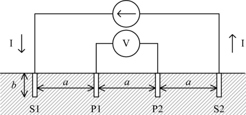
Figure 3. Wenner four-pin method. Image used courtesy of Stanišić and Radaković
- Schlumberger-Palmer method. A variant that reduces the need to move all four probes for each spacing, useful for large spacings and for increasing measurement sensitivity at depth.
- From measurements to models. Curve‑fitting of apparent resistivity versus spacing yields uniform, two‑layer, or multilayer soil models for use in IEEE 80 grid calculations or numerical solvers.
Ground System Verification
Fall‑of‑potential (3‑point) and clamp‑on tests estimate the substation’s resistance/impedance to remote earth; staged‑fault tests can directly measure GPR and surface voltage profiles where feasible. IEEE 81 also describes step, touch, mesh, and profile measurements on energized grids using low‑current injection with safety precautions.
Documentation and Compliance
Many jurisdictions explicitly require calculations and test reports demonstrating that step and touch potentials meet IEEE 80 criteria before energization or expansion of a substation.
Practical Design Considerations
Clearing time matters. Because the tolerable limits vary with \(\frac{1}{\sqrt{t_s}}\), faster protection (such as high‑speed relaying, communications‑assisted tripping) materially increases Etouch and Estep, sometimes avoiding costly additions to the grid.
Surface cover is a critical part of the grounding design. The Cs × ρs terms in the tolerable‑voltage equations show why well‑maintained crushed rock (clean, dry, adequate thickness) is an effective safety control. Degradation of the surface layer can reduce tolerable limits without any change to the grid.
Perimeter is critical. Worst‑case touch often occurs at corners or along the fence line. Denser conductor spacing, additional rods, and attention to fence and gate bonds reduce mesh voltages where public or maintenance access is possible.
Transferred potential must be addressed explicitly. Bonded metallic paths leaving the grid area can carry GPR offsite. Typical mitigations include isolation transformers, insulating joints, or fiber-optic links, consistent with OSHA and IEEE guidance.
Key Takeaways
Grounding/earthing design in substations is a safety‑critical process governed by measurable site data and well‑established criteria. The design objective is straightforward: ensure that every calculated step and touch voltage stays below the tolerable limits defined in IEEE Std 80 for the site’s clearing time and surface layer.
Achieving that objective efficiently requires accurate soil modeling, a well‑meshed grid augmented with vertical electrodes, high‑resistivity surface cover, and careful attention to perimeter and transferred‑potential interfaces. Materials and construction details—copper or galvanized steel conductors, robust bonds, and durable surface layers—translate calculations into dependable long-term performance.
When these elements are combined methodically, substations safely dissipate fault currents, minimize hazardous gradients, and provide a stable electromagnetic reference for protective relaying and control.