Facebook
 Google
 GitHub
 Linkedin
Primary Distribution Systems—Part 5: Planning for Today’s Grid
This article connects primary distribution to feeder upgrades (FLISR, right-sizing, DER/DCFC siting) for safety, quality, and restoration.
Designers of primary distribution systems—typically operating between 4 and 35 kV—are planning and operating in a new context shaped by rising load density, fast-growing fleets of distributed energy resources compliant with IEEE 1547, and high-power electric-vehicle charging that pushes multi-megawatt peaks onto feeders.
Effective planning now depends on feeder-specific hosting capacity analysis, time-series voltage and thermal assessments, and coordinated volt-VAR/volt-watt control that works with regulators and capacitor banks rather than against them. Urban underground segments and legacy assets introduce thermal and installation constraints that must be balanced with service-area growth targets and reliability expectations tracked by SAIDI/SAIFI (IEEE 1366).
On the protection side, bidirectional flows and limited inverter fault current shift emphasis toward directional elements, sensitive ground functions, updated reclosing per IEEE C37.104, and adaptive schemes exchanged via IEC 61850 GOOSE, often in coordination with microgrid controllers (IEEE 2030.7).
These drivers of practical feeder upgrades—automation (FLISR), conductor and transformer right-sizing, and siting strategies for DER and DC fast charging—must maintain safety, power quality, and restoration performance.
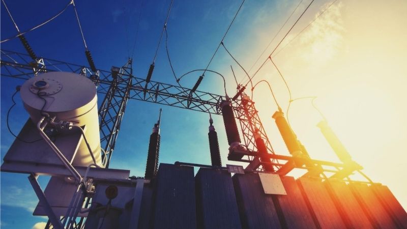
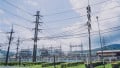
Power distribution. Image used courtesy of Adobe Stock
Increasing Load Density
Urban infill, electrified end‑uses, and growth in power‑intensive facilities (from cold‑chain warehouses to edge‑compute rooms) are driving higher kW per route‑mile on many feeders. As loading rises, thermal and voltage constraints often appear before conductor ampacity nameplates are reached, due to cumulative effects across cables, joints, and transformers.
Research and utility practice observe that underground circuits—common in dense cores—exhibit long thermal time constants. Their ratings and allowable overloads require attention to installation geometry, soil thermal properties, and load profiles. Dynamic rating concepts can help, but application in primary underground distribution demands careful validation and field measurements.
Planning countermeasures includes:
- Sectionalizing to shorten exposure and reduce voltage drop
- Converting radial feeders to meshed operation via normally open ties with faster FLISR schemes
- Deploying larger or parallel conductors in congestion zones
- Relocating or upsizing pad‑mounted transformers to better align with emerging load pockets
Guidance for industrial and commercial campuses emphasizes updated demand assessment and diversified loading methods to reflect modern end‑uses—inputs that feed utility studies when private developments interconnect at primary voltages.
Voltage and reactive power control should advance with load density. Smart distribution practice highlights distribution management applications—particularly volt‑VAR optimization—to reduce losses and maintain voltage within ANSI/NEMA C84.1 service bands under higher loading and evolving power factors. Coordinating regulator line‑drop compensation and capacitor dispatch with feeder reconfiguration logic becomes essential as switching schemes evolve.
Integration Of Distributed Energy Resources (DER)
Primary feeders increasingly host solar PV, battery energy storage, and controllable loads. IEEE 1547‑2018 defines interconnection and interoperability requirements for DER, including response to abnormal voltage and frequency, reactive power capability, and voltage/power control modes such as volt‑VAR.
The 2020 amendment (1547a) adjusted certain trip clearing time ranges to support broader adoption of Category III abnormal performance, reinforcing that DER remain connected during wider excursions to support system stability. These features improve grid support but also alter protection and voltage control behavior at the primary level.
Hosting capacity—how much DER can be added before violating limits—has matured into a planning practice used for generation and new large loads. Hosting capacity is estimated using static and dynamic methods, with dynamic approaches employing quasi-static time-series simulations to capture seasonal, diurnal, and location-specific behavior. Publicly available hosting capacity maps have expanded across states and utilities, offering early insight for siting DER and fast‑charging clusters at locations with available capacity.
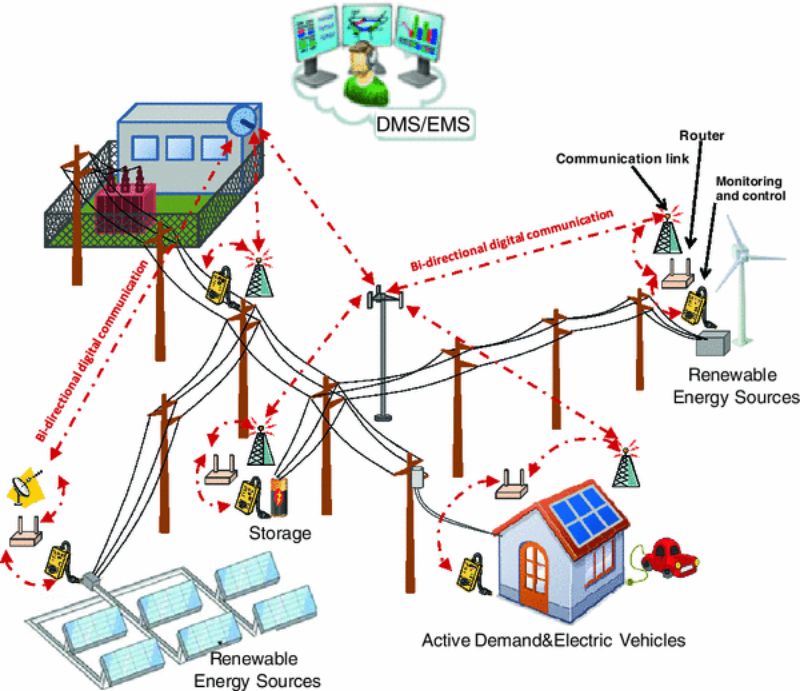
Figure 1. Distributed energy resources integration. Image used courtesy of DiFazio et al.
Distribution voltage behavior with high PV penetration illustrates the challenge: reverse power flow can cause regulator hunting, elevated line-end voltages, and miscoordination of legacy capacitor controls. Planners increasingly rely on advanced inverter settings aligned with IEEE 1547—volt‑VAR, volt‑watt, and frequency‑watt—to mitigate these effects, coordinated through feeder‑level objectives. The IEC 61850 series, particularly the DER information model (IEC 61850‑7‑420), provides a standardized data model and communication concepts that support interoperable DER management systems and utility operations.
Primary distribution that includes network secondaries or spot networks requires special attention when interconnecting DER due to anti‑islanding and fault-current paths. IEEE 1547 explicitly addresses DER on secondary grid and spot networks. Adherence to associated test and verification requirements is crucial for both design approval and commissioning.
Effects of EV Charging Loads
Light‑duty charging spans Level 1 and Level 2, up to roughly 19.2 kW per port, but the dominant planning shift arises from DC fast charging (DCFC). DCFC stations operate up to 500 kW per dispenser, with corridor programs specifying sites of at least four ports, each capable of 150 kW. These installations can create multi‑megawatt coincident demand when drivers cluster, stressing feeder headroom, service transformers, and upstream voltage regulation.
Connector standards matter for interconnection hardware and long‑term compatibility. The North American Charging System (SAE J3400) formalizes a combined AC-DC coupler widely adopted in recent models, providing a foundation for future power levels and interoperability advances. For heavy‑duty fleets, the megawatt charging system effort targets >1 MW charging to support commercial vehicle duty cycles. These trajectories intensify the need to assess primary feeder capacity, short‑circuit duty, and voltage sag performance under large step changes.
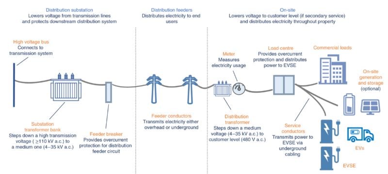
Figure 2. Electricity from grid to EV charging stations. Image used courtesy of National Laboratory of the Rockies/Bourlag et al.
Planning studies indicate that only select feeder locations can support high‑power DCFC without upgrades due to thermal limits and voltage constraints. National laboratory analyses recommend clustered‑load modeling with stochastic arrival patterns, managed charging to shape demand, on‑site storage to shave peaks, and placement guided by insights into hosting capacity. Because of predictable dwell and charging windows, fleet charging facilities benefit from managed charging strategies that align aggregate demand with feeder capability and tariff incentives.
EV load growth also affects power quality and service restoration. Fast charger inrush and rapid load shedding can interact with regulator deadbands and recloser sequences, so planning models should include representative charger dynamics and demand response triggers. Department of Energy guidance reinforces the basic service architecture—primary distribution stepped down to customer voltages—highlighting the importance of properly selecting protective devices and sizing breakers on the customer side to maintain thermal and voltage performance during EV operations.
Need For Adaptive Protection Schemes
Bidirectional flows from DER and the pulse‑like nature of high‑power charging alter the protection behavior on primary feeders. Inverter‑based resources contribute limited fault current compared with synchronous sources, potentially causing under‑reach in time‑overcurrent elements and unintentional fuse‑saver miscoordination.
Meanwhile, ride‑through obligations in IEEE 1547 mean that DER often remain connected during abnormal conditions, affecting fault-clearing and reclosing plans. Protection philosophies must account for altered current magnitudes and directions, evolving from static settings toward adaptive and communications‑assisted approaches.
Directional overcurrent, negative‑sequence elements, and sensitive ground protection can restore selectivity under reverse flow. Automatic reclosing guidance in IEEE C37.104 provides the framework for coordinating reclosers and sectionalizers on distribution lines. The 2022 revision includes updated practices relevant to modern automation.
Where feeder topology and communications allow, fast load and line switching integrated with protection (FLISR) shortens outage duration and limits cold load pickup stress on equipment. IEC 61850 standards documentation describes feeder use cases—including FLISR and directional fault detection—implemented with GOOSE messaging to share status and adapt settings among intelligent electronic devices (IEDs).
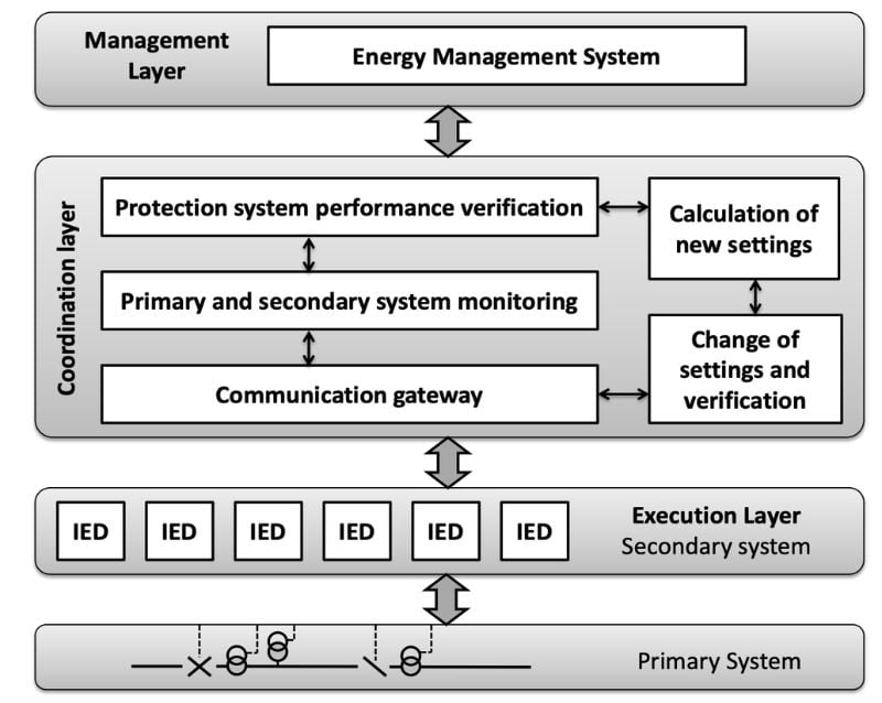
Figure 3. Architecture for adaptive overcurrent protection scheme. Image used courtesy of Coffele et al.
Adaptive protection requires an information backbone. The IEC 61850 series provides not just protocols but also semantic models and system configuration language to manage settings groups, publish status, and trigger scheme changes without wiring every interlock. As DER increases, the DER‑specific information model (IEC 61850‑7‑420) and distribution automation profiles help coordinate advanced inverter functions with feeder objectives, such as temporarily relaxing volt‑VAR parameters during feeder reconfiguration to avoid regulator hunting.
In parallel, microgrid controllers specified in IEEE 2030.7 can supervise islanding, black start, and reconnection sequences, coordinating with feeder relays to maintain protection integrity as operating modes change.
Time coordination is a practical consideration for adaptive schemes. High‑speed messaging and event alignment depend on robust network design and accurate time distribution; while not unique to protection, these factors influence the dependability of GOOSE‑based logic, fault location, and synchro‑check functions that protect equipment during rapid switching and DER transitions.
Conclusion
Primary distribution planning now operates in a space where growth, flexible generation, and new high‑power loads collide. Foundational references—voltage classes per ANSI/NEMA, transformer and equipment scopes, and reliability indices per IEEE 1366—still frame the analysis. The differentiator is precision: feeder‑specific data, time‑series evaluations, and interoperable controls that connect DER capabilities with utility objectives.
With hosting capacity methods guiding where and how much to add, connector and charging standards clarifying EV hardware, and protection guidance enabling directional and adaptive schemes, feeders can carry more, adapt better, and recover faster—without sacrificing safety or power quality.