Facebook
 Google
 GitHub
 Linkedin
Substation Design and Layout Planning—Part 3: Noise and Oil Control Issues
In the final part of this series, we examine substation design practices for managing two critical issues: oil containment and noise control.
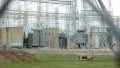
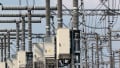
Designing and laying out a high‑voltage substation requires a blend of rigorous safety engineering, regulatory compliance, and sensitivity to community context. Two aspects often drive critical design choices: managing the risks associated with oil-filled apparatus—containment, fire, and spill control—and controlling audible noise at the property line.
This article consolidates recommended practices, standard references, and field‑proven solutions to support robust, defensible designs.
Oil Containment, Fire Protection, and Spill Mitigation
Containment Pits, Curbing, and Drainage Systems
Secondary containment begins with understanding oil inventory across transformers, regulators, and station service tanks. In the United States, the Spill Prevention, Control, and Countermeasure (SPCC) rule (40 CFR Part 112) applies when total above‑ground oil storage exceeds 1,320 gallons (counting only containers ≥55 gallons) and a discharge to navigable waters could reasonably occur. Applicability and the 55‑gallon container threshold are explicitly described by EPA; these thresholds typically capture most medium and large power transformers.
Designers can meet SPCC “general secondary containment” requirements through various means—sized pits, perimeter dikes with curb-and-trench systems, or shared collection basins—so long as the containment system is engineered to prevent a discharge from reaching navigable waters. For bulk storage, EPA requires a means to contain the entire capacity of the largest single container plus freeboard for precipitation; EPA guidance notes that facility drainage may be arranged to a common collection area serving multiple pieces of equipment. Calculations showing containment capacity are not mandated in the SPCC Plan but are recommended to demonstrate adequacy during inspections.
Oil-filled operational equipment in substations often sits within crushed‑stone yards. Properly detailed, the stone functions as a passive “quench” layer and helps restrict oil migration while maintaining electrical performance for grounding. Where passive containment is impractical, SPCC allows active measures—such as drain covers, sorbents, and spill kits—if they demonstrably prevent a discharge to waterways.
Beyond volume and hydraulics, reliable containment integrates controlled drainage and treatment. Typical features include:
- Normally closed valves on storm drains within the substation footprint, with lockout provisions and signage tied to the SPCC Plan.
- Oil–water separators or portable recovery when dewatering containment areas.
- Lined sumps and impermeable berm interfaces to avoid infiltration that could undermine neighbor parcels or utilities.
IEEE Std 980 provides additional engineering practice for designing oil containment and for integrating SPCC procedures specific to substations.
Firewalls, Separation Distances, and Fire‑Suppression Provisions
Fire exposure drives clear spacing, especially between large, oil‑insulated transformers and adjacent structures. Two frequently referenced documents are NFPA 850 (recommended practice) and FM Global Data Sheet 5‑4 (property loss prevention). While jurisdictional adoption varies, both sources articulate comparable principles: maintain spatial separation by oil volume and hazard class or interpose rated fire barriers when space is constrained.
- NFPA 850 guidance commonly cited in utility practice recommends either a 2‑hour‑rated firewall or spatial separation based on transformer oil volume; where firewalls are used, they should extend at least 1 ft (0.31 m) above the top of the casing/conservator and at least 2 ft (0.61 m) beyond the width of the tank and radiators (or to the edge of the containment).
- FM Global DS 5‑4 provides tabulated minimum separations (such as 25 to 50 ft for larger mineral‑oil units) and prescribes barrier extensions beyond components that can pressurize and fail under fault conditions; barriers are recommended to be 2‑hour rated, with specific over‑travel allowances in both height and width. These distances are measured from the edge of containment for larger oil volumes.
Where less‑flammable dielectric fluids are used (such as certain FM‑approved esters), both spacing and barrier needs may be reduced, enabling a smaller civil footprint—a design lever when sites are constrained near load centers.
Fire‑suppression provisions scale with risk and consequence:
- Deluge/spray systems targeted at radiators and tank surfaces to cool and limit escalation.
- Fixed or portable foam systems for spill fires within pits or sumps.
- Rapid de‑energization schemes and protective relaying to minimize fault energy and oil expulsion. The new IEEE 979 (2025) collates lessons learned from substation fires and current protection practices.
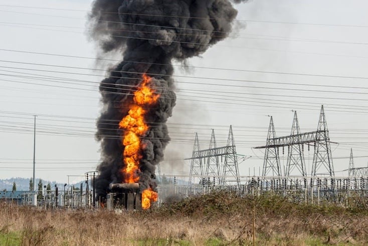
Figure 1. Fire at a high-voltage substation. Image used courtesy of T&D World.
Noise Control and Community Impact
Transformer and Reactor Noise Modeling
Power transformers and shunt reactors generate tonal components tied to twice the power‑frequency and its harmonics, with low‑frequency content that travels long distances. Accurate predictions rely on measured octave‑band sound power (or pressure) levels and standardized methods. For power transformers, audible sound tests are covered by IEEE C57.12.90 and IEC 60076‑10; these define factory and, where feasible, site measurement procedures to quantify source levels for modeling.
Propagation modeling should reflect terrain, ground impedance, atmospheric absorption, and diffraction around barriers. Many practitioners apply methods derived from widely used outdoor sound standards and validated barrier guidance, then calibrate predictions against spot measurements at sensitive receivers. Establishing clear design targets (such as tonal penalties, nighttime criteria) and documenting assumptions about operating modes (OA/FA/FOA cooling stages) are vital for producing credible outcomes.
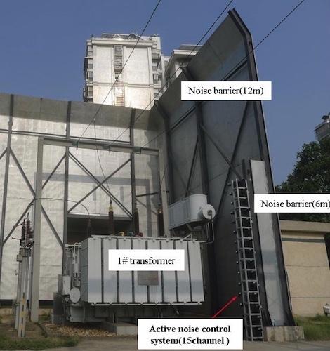
Figure 2. Active sound barrier at a substation. Image used courtesy of ResearchGate.
Barriers, Berms, and Enclosure Solutions
Noise control options fall into three broad categories: source reduction, path control, and receiver‑side measures.
- Source treatments include low‑noise transformer specifications (core stacking, step‑lap joints, optimized flux density) and quieter fans/pumps; however, industry studies indicate cost premiums for only modest reductions (on the order of 5–10 dB), making it important to evaluate noise-control options from a full lifecycle perspective when comparing equipment-based versus civil/architectural solutions.
- Path controls—barriers and berms—are the most common substation solution. Highway acoustics provides transferable rules‑of‑thumb: line‑of‑sight blockage generally yields about 5 dB insertion loss; each additional meter of height can add roughly 1.5 dB, with well‑designed systems achieving around 10 dB for first‑row receivers. Berms can outperform thin walls by approximately 1–3 dB given their bulk, though with larger footprints. These expectations align with empirical design ranges of roughly 5–12 dB for typical barriers. Absorptive facings help suppress reflections, particularly when parallel barriers exist.
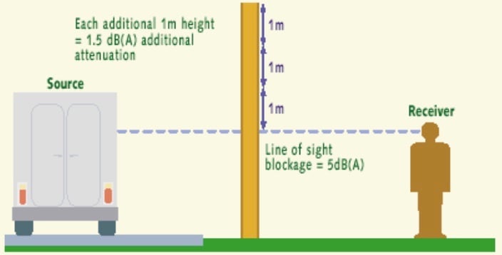
Figure 3. Noise reduction through a barrier. Image used courtesy of U.S. Federal Highway Administration.
- Enclosures and “box‑in” techniques can deliver large reductions when space and access permit. Field studies document transformer sound power reductions on the order of 10–15 dB by installing partial or full acoustic enclosures with adequate ventilation and maintenance access. Similarly, targeted barriers around individual transformers have achieved 9–14+ dB reductions at nearby receptors when designed with attention to low‑frequency performance and diffraction at ends.
Material choices matter. Dense, airtight panels provide high transmission loss; absorptive linings curb internal reverberation and reduce reflected energy toward receptors. For long, straight runs or where reflections from buildings are a concern, adding returns or wing walls at barrier ends improves low‑frequency insertion loss without excessive height.
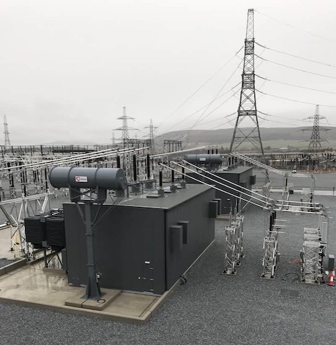
Figure 4. Transformer acoustic enclosure. Image used courtesy of Kimpton Acoustics.
Compliance With Local Noise Ordinances and Community Expectations
Unlike fire and spill rules, noise limits are typically set by local ordinance. Requirements range from absolute property‑line limits to “above ambient” thresholds, often with stricter nighttime criteria and added penalties for tonal noise. For example, New York City classifies “unreasonable noise” partly as sound 7 dB (A) or more above the ambient sound level at or after 10:00 p.m. and before 7:00 a.m. Many jurisdictions follow similar constructs.
As a planning context, the EPA’s 1974 “Levels Document”—not a regulation—identified day‑night average sound level (Ldn) of 55 dB as protective against widespread community annoyance, and 70 dB over 24 hours for preventing measurable hearing loss. These values still inform policy and public dialogue even though enforceable limits are local. Setting substation design targets to align with the local code while approaching or bettering Ldn 55 dB at sensitive facades tends to reduce risk of complaints, especially when tonal penalties are considered.
Community acceptance is also shaped by process. Early engagement—sharing predicted sound maps, barrier renderings, and construction‑hour commitments—often prevents mistrust. Post‑commissioning verification against the stated metric (such as Leq, L50, or ordinance‑specified “above ambient” criteria) should be planned, with contingencies for additional damping, barrier extensions, or fan speed controls if targets are narrowly missed.
Addressing These Elements Holistically
Robust substation layout emerges from integrating fire and environmental risk engineering with acoustical design and community expectations. On the oil side, well‑sized containment and drainage, coupled with credible SPCC documentation and firewall/spacing strategies from NFPA 850 and FM DS 5‑4, reduce the likelihood and consequences of rare but high‑impact events.
On the acoustics side, pairing standardized transformer sound data with realistic propagation models, and deploying barriers, berms, or enclosures calibrated to low‑frequency content, delivers predictable compliance at the fence line. Equally important, transparent design targets based on local ordinances—and informed by widely recognized public‑health benchmarks—build trust with stakeholders.
When these elements are addressed holistically from the concept stage, substations fit more reliably into tight sites, safeguard the environment, and integrate more effectively with surrounding communities.