Facebook
 Google
 GitHub
 Linkedin
Substation Transformers Explained
Learn about the different types of transformers in high-voltage substations by exploring their technical workings and the mathematical evaluations of essential parameters.
Substations play an important role in handling the electrical power consumed from generation to distribution. They also ensure that power is transformed and converted to suit different electrical needs. Transformers are used for various functions to accomplish that efficiently. This article explores the types of transformers used in substations and their role in power handling.
Substation Power Transformers
Power transformers reduce or increase the grid's voltage by stepping up or down the high voltage. These transformers ensure minimal losses in the distribution and transmissions that come from joule heating by ensuring that the transmission voltage is 345 kV and above and distributed at either 11 kV, 33 kV, or 66 kV. Lower distribution voltages can be implemented for residential use, while higher voltages are reserved for protectorate and industrial distribution networks.
![]()
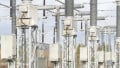
Figure 1. Illustration of a high-voltage substation. Image used courtesy of Unsplash
To better understand the inner workings of a substation's power transformation, power is evaluated using the voltage transformation equation by considering the transformer turns ratio (N). The voltage transformation equation compares the ratio of voltage and number of turns in the transformer's primary and secondary windings and is determined using:
\[\frac{V_{1}}{V_{2}}=\frac{N_{1}}{N_{2}}\]
where N is the turns ratio between the primary winding (N1) and the secondary winding (N2).
Example calculation: Consider a step-up transformer that increases the voltage in a substation from 11 kV (primary) to 220 kV (secondary). The secondary winding’s turns ratio can be easily evaluated as shown here.
Solution: Evaluate the turns ratio in which \(N=\frac{V_{1}}{V_{2}\)
\[N=\frac{V_{1}}{V_{2}}=\frac{220,000}{11,000}=20\]
Therefore, the turns ratio in the secondary winding is more than the primary winding by 20 times.
To better visualize the relationship between the secondary voltage (V2) and the turns ratio (N), consider the transformer voltage transformation graph below where, with the primary voltage at 11 k V, the secondary voltage rises steadily as the turns ratio increases.
![]()
Figure 2. Graph showing the transformation voltage from 11,000 V in a step-up transformer and the output voltage in relation to the turns ratio. Image used courtesy of Bob Odhiambo
Power transformers are not all entirely efficient, as power losses occur from copper and iron core associated with hysteresis and eddy currents. The resistance in the transformer's copper windings is responsible for copper losses as some of the energy is converted into heat, and this loss can be mathematically evaluated as shown in the equation below:
\[P_{copper}=I^{2}_{p}\times R_{p}+I^{2}_{s}\times R_{s}\]
For losses due to hysteresis and eddy currents, the iron loss equation is evaluated using the formula:
\[P_{iron}=V_{p}\times I_{on-load}\]
Rectifier Transformers in Substations
To minimize power transmission losses, substations are fitted with rectifier transformers that convert the high-voltage alternating current (AC) to high-voltage direct current (HVDC). When designing an HVDC system, the rectifier transformer technology, power rating, and voltage level are considered. The rectification technology uses converters like line-commutated converters (LCC) and voltage-sourced converters (VSC), which work distinctly in the rectification of power in HVDC systems.
In the basic configuration of an LCC, the conversion of high-voltage AC to DC is done using thyristors configured in thyristor bridges. The achievement of the commutation of the thyristors is made possible by the natural zero crossing of AC, which makes it less flexible in terms of control. This converter is suitable for interconnecting asynchronous AC systems and handling long-distance power transmission. To determine the resultant DC output voltage of the converter, we can mathematically evaluate it using the formula below, where (VAC) represents the voltage in the AC line.
\[V_{DC}=\sqrt{3}\times V_{AC}\]
Other essential parameters in the LCC power converter are the converter current (Iconv) and the resultant rectifier power (Prect). These parameters can be determined using the formulae below, where the current in the AC line is determined by (IAC).
\[I_{conv}=\frac{2}{\pi}\times I_{AC}\]
\[P_{rect}=\sqrt{3}\times I_{AC}\times V_{AC}\]
![]()
Figure 3. The LCC waveform graph shows a sinusoidal voltage and current with distinct commutation points. Image used courtesy of Bob Odhiambo
Unlike LCCs, VSCs can control the direction and magnitude of DC by using insulated gate bipolar transistors (IGBTs) that add more flexibility to the control of active and reactive power from integrating renewable energy sources into the grid. In VSCs, the AC line voltage is equal to the DC voltage. The AC line current is also equal to the converter current, as shown below:
\[V_{DC}=V_{AC}\]
\[I_{conv}=V_{AC}\]
The converter power in VCS is evaluated using the formula:
\[P_{conv}=\sqrt{3}\times V_{AC}\times I_{AC}\]
![]()
Figure 4. The VSC waveform graph displays a smoother voltage and current waveform, demonstrating its controlled and continuous operation. Image used courtesy of Bob Odhiambo
Phase-Shifting Transformers
For a stable and reliable grid, substations can use phase-shifting transformers (PSTs) to manage the electric power transmission by controlling the phase angle of power flow. PSTs can also regulate the voltage in the substation, further improving the voltage profile. PSTs are often used to connect asynchronous grid systems and HVDC transmission systems and control the power flow between AC and DC systems.
PSTs achieve power flow control by adjusting the turn ratio of the transformer using a tap charger. The phase angle adjustment can, therefore, be evaluated using the tap charger adjustment formula that determines the new voltage (Vout, new)
\[V_{out,new}=\frac{N_{turns,new}}{N_{turns,original}}\times V_{out,original}\]
The power flow is calculated by considering the sending and receiving end voltages, their phase angle differences ( ), and the reactance (X) of the transmission line. Power flow is therefore calculated using the formula:
\[P_{adjusted}=V_{sending}\times V_{receiving}\times\frac{sinsin(\theta+\Delta\theta)}{X}\]
where the difference in phase angle is represented by (∆ ).
Instruments Transformers
Acquiring an accurate reading of the power flowing in the systems is essential in substations. However, it is impossible to make a reading when the voltage is very high as it might damage the measurement instrument; that is where the instrument's transformer comes into play. This type of transformer reduces the substation's high voltage and current levels to a safer level that protective devices and measuring instruments can measure. Voltage transformers (VTs), also known as potential transformers (PTs), and current transformers (CTs) are the two main types of instrument transformers.
CTs are designed to measure high currents in a substation by stepping down the current in the power line. Accurate readings can be acquired by using the principle of electromagnetic induction. This type of transformer has a parallel connection between the primary winding and the power line. The secondary winding goes to the measuring instruments and the protective relay, and the amount of current reduction depends on the turns ratio between the secondary and primary windings. This makes CTs suitable for detecting overcurrent in the power line and metering applications.
When CT is exposed to elevated levels of primary current, its magnetic core becomes saturated. CT saturation can cause wrong readings, impacting the overall accuracy of the metering measurements. To account for deviations resulting from CT saturation, a parameter known as the accuracy limiting factor (ALF) is used for quantification and correct adjustments. Expressed as a ratio of the actual current flowing in the secondary winding to the rated secondary current of the CT, ALF is evaluated using the formula:
\[ALF=\frac{I_{actual}}{I_{rated}}\]
Unlike CTs, which use current for measurement, VTs or PTs measure voltage in high-voltage lines and can also be used for relay protection circuits. VTs lower the voltage to a safe level and, as in CTs, use electromagnetic induction in which the primary winding is connected to a high-voltage source while the secondary winding is connected to the protective relay and measuring instruments. As in CTs, VTs are also used for metering and protection purposes and can detect voltage abnormalities in the power line.
Regarding the accuracy of VTs, aspects like saturation and incorrect burden impendence can result in inaccurate or non-linear voltage measurements. To quantify the error between the actual transformer ratio and the rated ratio, the percentage error ratio (PRE) is evaluated using the formula:
\[PRE=(\frac{Actual\,Transformation\,Ratio-Rated\,Transformation\,Ratio}{Rated\,Transformation\,Ratio})\times100\%\]
Substation Transformer Takeaways
As transformer technology evolves, engineers employ different types to address various power engineering problems. Transformers used in substations are adaptive. Instrument transformers find their place in measurement and relay protection, while power transformers form a building block stepping up and down high voltages and currents in such stations.