Facebook
 Google
 GitHub
 Linkedin
Substation Design and Layout Planning—Part 1: Early Stage Decisions
In this new article series, we look at substation design and layout planning, starting here with early stage choices and physical layout.
Substations must deliver capacity, reliability, and safety within real-world constraints of land, environment, and budget. Effective planning integrates civil, electrical, and protection disciplines from the first site walk to the final equipment placement.
In this article, we will look at widely used practices and standards for early-stage decisions and physical layout, with considerations on how choices affect construction, operations, and lifecycle risk.
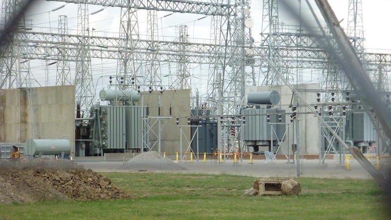
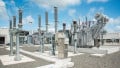
Figure 1. Electrical substation. Image used courtesy of Wikipedia.
Site Selection and Early‑Stage Considerations
Selecting the site sets the performance envelope for everything that follows. Early diligence should reduce technical risk, shorten permitting, and avoid expensive rework in detailed design.
Geotechnical Conditions, Soil Resistivity, Flood Risk, and Environmental Constraints
Substation foundations and structures depend on competent soils; expansive clays, liquefaction-prone sands, and high groundwater complicate grading, drainage, and foundation design. In parallel, grounding safety hinges on measured soil resistivity: low-resistivity soils ease grid design while high-resistivity or layered soils often require more conductors, deeper rods, or ground wells to control touch and step voltages during faults. Perform field testing (such as Wenner four-point) and integrate results into grounding studies per IEEE 81 and IEEE 80.
Flood exposure remains a significant threat to substation availability and personnel safety. FEMA Flood Insurance Rate Maps and the National Flood Hazard Layer provide official mapping of Special Flood Hazard Areas (the 1% annual-chance floodplain). Siting above mapped hazards—or implementing elevation, diversion, and properly sized oil-containment—reduces outage and environmental risk and eases permitting.
Environmental constraints such as wetlands, protected species, and cultural resources can dictate footprints or mitigation. Early screening, combined with a conceptual erosion, sediment, and spill-control strategy, accelerates later approvals and aligns with utility and federal program guidance on substation site design.
Access, Constructability, and Proximity to Existing Transmission Corridors
Construction logistics must accommodate transformer deliveries, cranes, and stringing equipment. Evaluate haul routes, turning radii, and staging areas at the outset. Proximity to existing corridors shortens new right‑of‑way, reduces schedule risk, and can lower interconnection costs, but it also introduces constraints on clearances, outages for cutovers, and switching windows. Planning guides for rural and transmission utilities outline road sections, drainage, fence lines, retaining structures, and oil containment that ease buildout and future maintenance.
Land‑Use Restrictions, Permitting, and Right‑of‑Way Requirements
Zoning, easements, and noise/light ordinances affect control‑house placement, night work, and shielding. Where federal approvals apply, anticipate NEPA review and associated studies. Right‑of‑way negotiations benefit from early, survey‑based route definitions and clear, code‑driven clearance envelopes that will later be mirrored by layout drawings and field staking.
Taken together, these steps de‑risk the project’s civil and grounding baseline, clarify permitting scope, and bound the electrical one‑line chosen for the yard.
Spatial Arrangement and Equipment Layout
Physical layout translates the chosen one‑line into steel and conductors. Decisions on bus scheme, equipment spacing, and separation directly affect reliability, safety, and lifecycle cost.
Bus Configuration Options
Bus topology trades capital for maintainability and contingency performance:
- Single bus: lowest initial cost and simple protection; a bus fault or maintenance de‑energizes all connected circuits.
- Ring bus: one breaker per circuit with improved reliability; however, operating in an “open ring” reduces security and must be managed carefully.
- Breaker‑and‑a‑half: high reliability and flexibility, allowing removal of any single breaker without losing connected circuits; higher cost and footprint.
- Double breaker–double bus: very high reliability at premium cost; most often justified at large generation injection points. Independent evaluations and utility practice documents provide pros/cons and evolution paths (such as starting as a ring and expanding to breaker‑and‑a‑half as circuits grow).
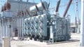
Gas‑insulated substation (GIS) and hybrid GIS/AIS can dramatically shrink footprints and ease siting in urban or constrained locations. GIS yards frequently require 10–20% of the land area of an equivalent air‑insulated (AIS) yard; hybrid substation modules can reduce space 50–70% relative to conventional AIS. These gains come with higher unit costs and specific lifecycle considerations for the insulating medium.

Figure 2. Gas insulated substations significantly reduce footprints compared to AIS. Image used courtesy of Roxtec.
Equipment Spacing for Operation, Maintenance, and Arc‑Flash Safety
Air clearances around live parts and to ground must meet insulation coordination objectives and support safe operation. IEEE 1427 provides recommended electrical operating and safety clearances across 1 kV to 800 kV for open‑air bus assemblies and is a primary reference when laying out bus heights, phase spacing, and bay widths. Spacing should be checked against equipment BIL/BSL ratings, arrester locations, and expected overvoltage environment.
Human‑factor clearances—walkways, equipment access, and door swing envelopes—should be coordinated with working distances established by arc‑flash and shock hazard analyses. For approach distances during energized work, OSHA 29 CFR 1910.269 defines minimum approach distances (MAD) by voltage and exposure, with altitude corrections; these boundaries must be respected in the physical arrangement and in maintenance procedures.
For incident‑energy calculations and arc‑flash boundaries, IEEE 1584‑2018 remains the industry method of record, informing labels, PPE selection, and working distances documented in switching procedures and job safety plans.
In practice, the yard plan must let crews rack out breakers, replace CTs/PTs, lift bushings, and set portable grounds without encroaching on guarded distances. Service bays and removable fence panels at transformer positions, plus cable trench lids designed for frequent access, prevent “work‑around” habits that erode safety margins.
Physical Separation for Reliability
Separation is as much about preventing common‑mode failure as it is about meeting code. Two areas deserve special attention:
Fire separation between oil‑filled transformers and between transformers and buildings
NFPA 850 recommends, unless a performance analysis dictates otherwise, either fire walls or spatial separation based on oil volume. Common criteria include two‑hour fire walls extending above and beyond radiators or line‑of‑sight distances such as 25 ft for 500–5,000 gallons and 50 ft for more than 5,000 gallons of oil. These measures reduce radiant heat impingement and projectile risk from failing bushings.

Figure 3. Separation distances for oil-filled transformers in terms of oil volume. Image used courtesy of T&D World.
Cable routing and control‑building placement
IEEE 979 and utility guides emphasize limiting fire spread and single‑event damage by physically separating AC station service, DC battery/charger circuits, and critical protection/control cabling in trenches or ducts with fire stops at building penetrations. Cable routing should be kept clear of transformer-deluge discharge zones and oil-containment flow paths. Locating the control house outside the highest fire exposure zones and away from main spill trajectories supports both fire pre‑plans and post‑event restoration.
For GIS, the compact layout further concentrates risk in enclosures. While GIS reduces outdoor clearances and exposure to contamination, planners should weigh the environmental implications of insulating gases. SF6—the legacy medium—has a very high global warming potential (GWP ~23,500 over 100 years) and a long atmospheric lifetime; designs and procurement strategies increasingly consider alternatives and enhanced leak‑management.
Constructability and expandability within the layout
The most reliable yard is also straightforward to build and extend. Early inclusion of construction sequence—backfeed points, temporary grounding, and commissioning test access—reduces outages and field changes. Leave space for future transformer bays, allow bus taps for additional feeders, and plan spare cable ducts and panels in the control house so expansions do not compromise existing protection schemes or cable separation criteria. Guidance documents provide typical expansion approaches for common bus schemes and detail foundations and structures to support staged buildouts.
Control house and auxiliary systems
Control‑house siting should shorten low‑level signal runs to minimize CT/VT burden and digital channel lengths while respecting fire and spill zones. Rooms are organized to isolate batteries and chargers, maintain NEC/NFPA egress and working‑space requirements, and facilitate fiber entry from multiple directions with protected paths. HVAC sizing accounts for summer commissioning with all panels energized and doors closed, plus redundancy where outages are unacceptable. Standard references align these architectural choices with protection, communications, and SCADA requirements.
Key Takeaways
Successful substation projects reduce uncertainty up front and design physical spaces that make safe, reliable operation the default. Site selection should balance geotechnical realities, measured soil resistivity, and flood mapping with environmental and permitting constraints. The electrical one‑line and bus topology must be matched to reliability objectives, land availability, and lifecycle costs, with GIS or hybrid solutions considered where footprint dominates.
Layouts should incorporate electrical clearance rules, enforceable approach and arc‑flash boundaries, and purposeful fire and cable separation to avoid common‑mode failures. Documented decisions, based on established standards, help owners, designers, and constructors move in lockstep from concept through energization and long‑term maintenance.