Facebook
 Google
 GitHub
 Linkedin
Designing Switch-mode Power Supply Board Layouts
This article explains the basis for achieving an optimized board layout, a critical aspect in the design of switch-mode power supplies.
Passive Components in the Switching Regulator IC
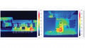
Figure 1 illustrates the circuit of an LT8640S evaluation board—a step-down (buck) switching regulator that can tolerate input voltages of up to 42 V and is designed for output currents of up to 6 A. All components have been placed very compactly. Placing the components as close together as possible on the board is a general recommendation. While this statement is not false, it is also not particularly suitable if the goal is to obtain an optimized board layout.
In Figure 1, there are quite a few (11) passive components surrounding the switching regulator IC.

Figure 1. The board of an LT8640S switching regulator with closely spaced components and, thus, a compact board layout. Image used courtesy of Bodo’s Power Systems [PDF]
Which of these passive components have priority over the others in the placement and why?
In a switching regulator PCB design, the most important rule is to route the traces that carry high switched currents to be as short as possible. If this rule is successfully implemented, a large part of the board layout for a switching regulator will be addressed properly.
Critical Paths in Switching Regulator Topology
What is the easiest way to implement this board layout?
The first step is determining which paths in a switching regulator topology are critical. In these paths, the current flow changes with the switch transitions. Figure 2 illustrates a typical circuit for a step-down converter (buck topology). The critical paths are shown in red. They are connecting lines in which either the full current or no current flows, depending on the state of the power switches. These paths should be as short as possible. For a buck converter, the input capacitor should be situated as close as possible to the VIN and GND pins of the switching regulator IC.
Figure 3 illustrates a basic schematic diagram of a circuit with a boost topology. Here, a low voltage is converted to a higher voltage. Once again, the current paths in which the current flow changes with switching of the power switches are shown in red. Interestingly, the placement of the input capacitor is not critical at all. The most crucial is the placement of the output capacitor. It must be as close as possible to the flyback diode (or the high-side switch) as well as to the ground connection of the low-side switch.

Figure 2. A schematic of a step-down switching regulator and paths with rapidly changing currents are shown in red. Image used courtesy of Bodo’s Power Systems [PDF]

Figure 3. A schematic of a step-up switching regulator and paths with rapidly changing currents are shown in red. Image used courtesy of Bodo’s Power Systems [PDF]
After that, any other switching regulator topology can be examined to determine how the current flow changes when the power switches are switched. The classic method involves printing out the circuit and drawing the current flow using three different colored pens. One color indicates the current flow during the on-time—that is, when the power switch is conducting current. The second color shows the current flow during the off-time—that is, when the power switch is switched off. And finally, the third color is used for all paths marked either only in the first or second color. The critical path, in which the current flow changes with the switching of the power switches, can then be clearly identified.
The Most Important Rule of Board Layout Design
Inexperienced circuit designers often consider the board layout for a switching regulator to be black magic. The most important rule is to design the traces, in which the current flow changes with the switch transitions, to be as short and compact as possible. This can be explained easily, follows logical relationships, and is the basis for an optimized board layout in a switch-mode power supply design.
This article originally appeared in Bodo’s Power Systems [PDF] magazine.
Related Content