Facebook
 Google
 GitHub
 Linkedin
Resonance in High Frequency Grounding and Bonding Networks
Learn about the impact of resonance in grounding and bonding conductors.
When dealing with grounding and bonding with high-frequency signals, the conductors’ impedance is of paramount importance. The conductors used for bonding and grounding exhibit distributed capacitance and inductance along their length and may resonate at a particular frequency – or its multiples – behaving like open-circuited conductors and becoming useless for their intended purpose.
Resonant Circuits
Circuits that behave towards a narrow range of frequencies differently from all other frequencies are of significant interest. These are resonant circuits.
The input impedance of a resonant circuit attains a sharp minimum or maximum at its resonant frequency. In contrast, its changes outside a small band of frequencies on every side of the resonant frequency are much lower.
Resonant circuits have many practical applications (laser, amplifiers, oscillators, filters, antennas), but they may become a severe difficulty for grounding and bonding use.
Circuit analysis shows that any passive lumped element linear n-port electric circuit containing a minimum of one inductor and one capacitor – and a resistor that does not introduce excessive dissipation – can exhibit the resonance phenomenon. The resonant frequency of any resonant circuit is the one at which the input impedance is real.
The simplest analytical expression for resonant behavior in a lumped element circuit consists of a series connection of an ideal resistor, an ideal inductor, and an ideal capacitor. In this arrangement, the resonant impedance magnitude is identical to the minimum value of the input impedance.
Of more practical importance than the series resonant circuit is the parallel resonant circuit — the series circuit dual. The input impedance magnitude of the parallel resonant circuit passes through a maximum value at or near the resonant frequency at which it is real. This behavior is also known as an antiresonance.
Resonant Transmission Lines with Short-circuit Terminations
The analogies with the familiar resonant properties of lumped element resistance- inductance-capacitance circuits help appreciate transmission line circuits’ resonant properties.
Grounding and bonding networks resemble short circuits, and therefore only the resonant transmission lines with short circuit terminations are relevant in this analysis.
The input impedance of a transmission line section with short-circuit termination will be real at all frequencies, for which l/ʎ=n/4 or l=n∙ʎ/4.
Where
l = line length
ʎ= wavelength
n = any integer
Then, the frequencies at which the input impedance is real are those for which a line length is an integral number of quarter wavelengths. The input impedance has a maximum value when n is odd ( ʎ/4,(3/4)ʎ,(5/4)ʎ,…), and a minimum value when n is even (ʎ/2, ʎ, …).
Comparing lumped elements, it follows that when the input impedance of a low-loss transmission line section with short circuit termination is a maximum, it displays the resonance behavior of a parallel resonant circuit. Likewise, when the input impedance is a minimum, it shows the resonance behavior of a series resonant circuit.
Summarizing, the input impedance varies similarly to a parallel lumped element resonant circuit in the vicinity of the frequencies for which a line length is an odd number of quarter wavelengths. It goes like a series lumped element resonant circuit in the vicinity of the frequencies for which a line length is an integral number of half wavelengths.
Example:
7.5 m of bare wire in the air, ground a metallic computerized control cabinet in a production facility. Compute the resonant frequencies for high-frequency waves traveling in the wire. Indicate the type of resonance and plot approximate impedance vs. frequency curves. Compute the wavelength for f = 60Hz. Derive conclusions from the results. For simplicity, assume the propagation speed = c = speed of light.
l = 7.5 m
ʎ∙f=c=300∙10⁶m/s
- If l=7.5 m=ʎ/4, then ʎ=30m and f=10Mhz
- If l=7.5m= ʎ/2, then ʎ=15m and f=20MHz
- If l= 7.5m=¾ ʎ, then ʎ=10m and f=30MHz
- If l=7.5m=ʎ, then f=40MHz
- If f=60Hz, then ʎ=5,000 km and l=1.5∙10¯⁶ʎ
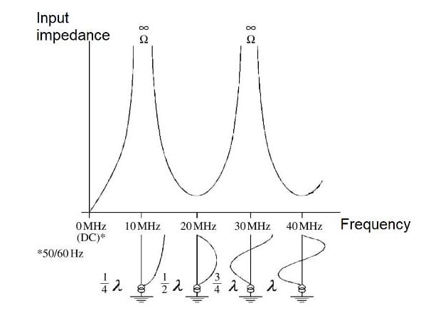
Figure 1. Impedance vs. frequency for a 7.5 m grounding conductor. Image based on G. Vijayaraghavan, et al., 2004.
The input impedance is maximum at 10 MHz and 30 MHz, parallel resonance, and minimum at 20 MHz and 40 MHz, series resonance.
At the frequencies in the vicinity of 10 MHz (ʎ/4) and 30 MHz (3/4)ʎ, the wire acts as an open circuit and cannot equalize the potentials at its ends; it is, therefore, useless as a grounding or bonding conductor.
At the frequencies in the vicinity of 20 MHz (ʎ/2) and 40 MHz (ʎ), the impedance is low, and the wire does equalize the potentials at its ends.
At direct current (DC), 50Hz, and 60Hz, the wire length is a tiny fraction of the wavelength. The impedance value is marginal, and there is no chance of resonance. The wire is suitable for DC and power frequencies.
Grounding and Bonding Circuits Acting as Antennas
An antenna is a particular electric circuit capable of radiating and receiving energy through space in electromagnetic waves.
The wires, rods, tubing, and other metallic elements used for grounding and bonding may behave as antennas, radiating energy that may be received by susceptible victim circuits, producing several forms of noise. It happens when the metallic elements’ dimensions become appreciable compared with the wavelength of the frequency in use. The frequency content of the source depends on the type of circuit and the speed of its components.
The field strength is directly proportional to the current magnitude and the most considerable current flows when the circuit resonates at the operating frequency. Then, the radiation will be the greatest when the circuit is resonant.
A ground conductor should be an inefficient antenna to be useful.
Grounding Conductor Length
The most valuable performance of the grounding and bonding conductors is at frequencies well below the first resonance. When the electrical path is below ʎ/4, the short-circuited transmission line’s input impedance has a value ranging from 0 to infinite ohm.
Bonding and grounding conductors’ length should be lower than ʎ/4 to avoid resonance, prevent radiation, maintain a low impedance, and ensure that they will equalize the potentials along their span. The recommended practice is limiting the conductor length to 0.05 ʎ or (1/20)ʎ.
Grounding circuits for high-frequency systems should use multiple conductors with different lengths so that the combined grounding system does not resonate for any frequency. A practical and straightforward method to accomplish this is using the multipoint grounding technique with short conductors.
Another method uses a signal reference structure (SRS), which will create many low impedance paths with negligible potential differences between any two points on the mesh for a broad range of frequencies.
About Resonance in High-Frequency Grounding and Bonding Networks
Resonance is an advantageous property for many circuit applications, but not for grounding.
The input impedance presented by the grounding and bonding conductors at resonance is high or low, depending on whether the circuit is parallel or series resonant. Resonance occurs at values equal to integer multiples of ʎ/4 (ʎ/4, ʎ/2, (3/4)ʎ, ʎ, etc.).
Grounding and bonding conductors, depending on their lengths relative to the wavelength, may work as antennas picking up or radiating noise.
The grounding and bonding conductors’ lengths should be a small fraction of the wavelength at the signal’s operating frequency. The recommended maximum size is ʎ/20.