Facebook
 Google
 GitHub
 Linkedin
Efficient Induction Heating Designs
This article discusses designs, topologies, and other approaches for efficient induction heating.
A frying pan, cut in half, sits on a cooking hob with an egg carefully broken into its center. The half on the pan has a perfectly cooked, glistening white, while the remaining half is clear and uncooked. It’s a powerful image that makes abundantly clear how much more efficient induction hobs are over alternative cooking appliance technologies. The message: induction heating places the energy where it is needed.
The semiconductor industry has responded to the demand for induction heating appliances by continuously tuning and improving the switching technology required for its optimal implementation. Thus, induction technology commonly also appears in rice cookers, milk frothers, and hot-plates.
Tackling Induction in Heating Applications
It is the principles of the common transformer that form the basis for induction heating applications. However, whereas a transformer induces a current in a secondary coil from a primary coil, an induction heater uses the primary coil to induce current in the cooking vessel itself. This ensures that the resulting heating effect is concentrated precisely where it is needed. It is the Eddy currents that are induced in the material of the cooking vessel that resulting in the heating effect that is known as Joule heating. High resistance is offered by vessels made of magnetic materials such as stainless steel and iron, while non-magnetic materials, such as aluminium and copper, provide less resistance.
Due to the high frequencies used, the current in the primary coil flows principally in the surface of the conductor, a property known as the skin effect. Induction heating coils make use of a special type of copper wire, known as litz wire, that is made up of many thin individual strands. This has the effect of increasing the surface area of the coil, thereby reducing the AC resistance.
Topology Choices and Their Functions
There are several approaches to topology choice but, due to price pressure in many of the markets targeted by these applications, the Single-Ended Parallel Resonance (SEPR) circuit is a common choice (figure 1). This softswitching topology makes use of a resonant tank network consisting of a capacitor, Cr, and the litz coil, Lr. An IGBT, operating under zerovoltage switching (ZVS) conditions together with parallel diode, complete the design. Rather than implementing a discrete approach, the diode is typically integrated into the IGBT, with the characteristics of the diode being optimised to the needs of this type of circuit. Switching frequencies of 20 – 30 kHz ensure any noise is outside audible range, making this circuit suitable for magnetic cookware. Higher frequencies may also be used as part of a soft-start function.

Figure 1: A single ended parallel resonance (SEPR) circuit is typically used for voltage-resonant circuits.
The operation of the voltage-resonance circuit is broken down into four time periods (figure 3) and is applicable for the case that the start-up process has been completed (i.e. Cr is full charged):
-
T1 – The cycle starts with Q1 being turned on, allowing current to flow from Cm through Lr and Q1 and causing the current flowing to increase linearly until it reaches the desired level. During this time the voltage across Cr is clamped to the voltage across Cm.
-
T2 – Next Q1 is turned off, causing Lr and Cr to go into resonance. The peak resonance voltage attained increases proportionally to the on-time T1.
-
T3 – The resonance current flow changes direction, causing the voltage over Cr to decrease.
-
T4 – The polarity of the voltage across Cr now reverses. When it exceeds the voltage across Cm, current starts to flow through the diode bringing the polarity and voltage of Cr back to that of Cm.

Figure 2: The four phases of operation in a SEPR voltage-resonance design.
The rating of the IGBT will depend on the voltage peak Q1 sees, which for 100 VAC supplies will require a VCES rating of between 900 and 1200 V, or 1350 to 1800 V for 220 VAC supplies.
As power requirements increase, a half-bridge current resonance approach using two IGBTs with integrated diodes is typically used (figure 3). Such designs can also support ‘all metal’ use, where switching frequencies of 80 to 100 kHz can even support the use of non-magnetic cooking vessels. The resonant circuit is implemented as a series LC or LCR construction.

Figure 3: Induction heater half-bridge circuit with current-resonant series LC.
The operation of this circuit can also be described in four phases (figure 4), once the start-up process is completed, as follows:
-
T1 – The upper switch, Q1, is turned on, resulting in a current flowing from the capacitor, Cm, into the resonance current circuit Cr-Lr.
-
T2 – Switch Q1 turns off, leaving Cr to charge due to the current flowing from Lr through the lower switch’s diode.
-
T3 – Switch Q2 is turned on, allowing a resonant current to flow from Cr through Q2 and into Lr. At this point, the VCE of Q2 is clamped at the forward voltage of the parallel (or integrated) diode, thereby enabling a ZVS.
-
T4 – Switch Q2 is turned off, allowing a freewheeling current to flow from Lr through Cr, the diode parallel to Q1, and Cm. At this point, the VCE of Q1 is similarly clamped to the forward voltage of the parallel (or integrated) diode, enabling ZVS for the next phase, T1.

Figure 4: The four phases of operation in a half-bridge current-resonance design.
As a result, the peak voltages are limited to the sum of the peak AC input voltage, allowing IGBTs to be specified with a VCES of 600 to 650 V for inputs of 220 VAC. The higher currents involved preclude the use of this design with 100 VAC inputs.
Selection of Suitable IBGTs for Use in Induction Heating Appliances
It is clear that appropriate understanding for the voltages generated across VCES is a critical factor in IGBT selection. The gate drive voltage, VGES, also needs review. This is typically operated at 18 V to reduce power losses in the IGBT. However, fluctuations in mains supply in many markets, sometimes as much as 20%, means that designers will need to ensure that the datasheet indicates enough headroom for these parameters. Thermal parameters, such as Rth(j-c), provide guidance on the cooling concept required, while tests should be undertaken on electromagnetic compatibility (EMC), especially the turn-off at lower testing frequencies.
Another critical aspect to review is the IC(sat) rating, a parameter that is relevant during the short circuit currents that flow to charge Cr at initial power-up until its voltage matches that on Cm. Finally, the forward-biased safe operating area (FBSOA) maximum permissible collector current, VCE, should be checked for different pulse widths.
Punch-through (PT) IGBTs are the device of choice in such applications, supporting higher switching frequencies than non-PT types of the past. The latest advances have thinned the P collector layer to create structures known as field stop (FS) IGBTs. This allows the creation of an N layer to enable a reverse conducting (RC) body diode, leading to RC-IGBTs. With a reduced tail current, they are well suited to softswitching circuits. Toshiba’s latest RC-IGBT, the GT20N135SRA, is a new generation of device with support for 20 A @ 100°C and 1350 V. This is ideal for 220 VAC supplied induction heating applications for 2200 W, medium-capacity appliances.
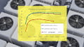
Compared to previous generation devices, the short-circuit current, IC(sat), is limited to around 150 A at 100°C. During the start-up phase of the circuit, as Cr is charged, this help to reduce collector saturation current and suppress voltage oscillation (figure 5). The wider FBSOA also means that higher currents can flow, but this must be balanced against some of the losses being converted into heat. The GT20N135SRA has a maximum Rth(j-c) of 0.48 °C/W so, assuming the IGBT needs to dissipate 35W in an appliance implementation, the junctioncase temperature would be around 6°C lower than previous generation devices (GT40RR21 – 0.65 °C/W).

Figure 5: The short-circuit collector saturation when Cr is not charged is significantly improved in the GT20N135SRA (right) compared to the previous generation of IGBTs (left) and results in reduced oscillation (red circle)
The improved N layer has also brought a reduction in the forward-voltage, VF, of 0.5 V compared to previous generation devices. With a typical value of 1.75 V at 25°C defined, this reduces losses and improves efficiency. The turn-off operation of IGBTs can make it challenging to meet the CISPR standard, requiring a resistor in the gate path to slow switching speed. However, this results in increased losses. Around 10 dB more margin at 30 MHz is now achieved without such a resistor in the same table-top application with the GT20N135SRA, providing a better trade-off between radiated emissions and power dissipation (figure 6).

Figure 6: An improved turn-off results in 10dB more CISPR margin at 30 MHz for the same appliance.
Summary
While induction heating appliances provide more efficiency and better control compared to many alternative technologies, the onus falls upon the design engineer to deal with the complexity of the control electronics to implement them. The semiconductor industry has responded with IGBT switching devices that, over several generations, have continued to improve the characteristics that are critical for optimal performance, from heat dissipation and EMC, to voltage and current capability and improved reverse conducting body diode.
The GT20N135SRA, Toshiba’s latest generation of RC-IGBT, makes it easier to bring products to market that fulfil radiated emissions tests, while also being more efficient. While optimised for 220 VAC current resonance applications, future products will expand to cover the higher-current needs of larger cooking vessels and higher voltages occurring in 100 VAC appliances.
This article originally appeared in the Bodo’s Power Systems magazine.