Facebook
 Google
 GitHub
 Linkedin
Reducing Inverter Cost with CurrentMeasurement Integration in Power Modules
This article describes the impact of introducing internal shunts to the power module in inverters in the power range above 75 kW.
Cost reduction and increased power density combined with long lifetimes are the main challenges for the development of new generations of inverters. For instance, the electrical performance of IGBTs and diodes, and interconnection technologies has been consistently improving over time. A further potential for cost reduction is the introduction of shunts for current measurement internal to the power modules, replacing Hall-effect sensors measuring the AC current in inverters at power levels above 75 kW.
This article describes the impact of introducing internal shunts to the power module in inverters in the power range above 75 kW, specifically: cost reduction, performance improvement, and simplified inverter design. Current sensing is required for speed/torque control, and protection functions like overcurrent and short-circuits detection. The type of current measurement is dependent on different factors, for example, power level, cost targets, accuracy requirements, and available physical space.
In reference [1], the different possible current-measurement technologies are described and discussed in detail. They can be summarized in Table 1:
| Shunt module + ΔΣ modulator | Hall-effect sensor closed loop | Hall-effect sensor open loop | |
| Accuracy | high | high | medium |
| Cost | low | high | medium |
| Physical space required | low | very high | high |
| Assembly/ Mounting effort |
Very low Some parts on PCB |
high mounting, cable & plug connection |
high mounting, cable & plug connection |
| Isolation | reinforced via ΔΣ modulator | reinforced w/o additional measures | reinforced w/o additional measures |
| Step response time | Configurable tradeoff between resolution and response time |
typ. <1µs | typ. -2...4µs |
| Power supply | typ. unipolar 5V, <20mA |
typ. bipolar |
typ. unipolar 5V, 20mA |
Table 1: Summary of the main difference between three different approaches for current measurement.
Innovation
The implementation of shunts inside the IGBT modules opens the door for the use of shunts and delta-sigma modulators with 250 mV input voltage in the inverter power range above 75 kW. The development of new delta-sigma modulators that can operate with an input voltage of 50 mV [2] will help to reduce the power losses in the shunts for future systems. Infineon has developed a portfolio of modules with integrated shunt resistors in the AC output. Table 2 gives an overview of the available products at present.
| Ic [A] | 1200V | 1700V |
| 75 | IFS75B12N3E4_B31 | |
| 100 | IFS100B12N3E4_B31 IFS100B12N3E4P_B11 |
IFS100B17N3E4P_B11 |
| 150 | IFS150B12N3E4_B31 IFS150B12N3E4P_B11 |
IFS150B17N3E4P_B11 |
| 200 | IFS200B12N3E4_B31 | |
| 300 | IFS300B12N3E4P_B11 | IFF300B17N2E4P_B11 |
| 300 | IFS300B12ME4P_B11 | |
| 450 | IFS450B12ME4P_B11 | |
| 600 | IFS600B12ME4P_B11 | |
| IFS-6-pack, IFF-2-pack | ||
Table 2: Overview with the product line-up of available Infineon IGBT modules with integrated shunts.
An important property of the shunt is its temperature stability that enables a current measurement with excellent linearity over a wide temperature range. It can be shown that the shunts used by Infineon feature a temperature drift of less than ±0.3 percent. Details about the shunts deployed are described in Reference [3].
Inverter Design – the Reduction of Parts Quantity
The simplification of an inverter design is one crucial requirement during the development of new inverter generations with the target of reducing the bill of materials and the production costs, as well as to increase system reliability and power density. The fact that current measurement can be integrated with the power electronic module helps significantly to address these topics.
Figure 1 shows a drawing of a typical 240 kW three-phase system with Hall-effect sensors as well as the improved system utilizing internal shunt resistors.

Figure 1: Example of a 240 kW three-phase system: (a) using Hall-effect sensors, (b) using internal shunts and (c) the difference in parts between the two. The parts illustrated in figure (c) can be saved.
Using internal shunts, the overall parts’ count can be reduced. Often the output busbar design can be simplified, as it does not have to meet the constraint of fitting through the Hall-effect sensor aperture. The screws, which were needed for the connection of the Hall-effect sensor, are saved as well as the cable that connects the Hall-effect sensor to the PCB. In combination, these changes lead to a reduced bill of material and a production-time saving. This will reduce the inverter costs and improve the system reliability.
Inverter Design – Thermal Aspects
The maximum temperature of the busbar has to be taken into account if using a Hall-effect sensor. Typical sensors are specified to operate below 85 or 105 °C housing temperature, depending on the device used; see References [1], [4]. For a solution using shunts, the thermal aspects are different. The working principle of the shunt current measurement is that the load current flows through a resistor, and the resulting voltage drop is measured. This leads to the generation of power losses in the shunt resistor. The inverter designer has to take care not to exceed the maximum shunt temperature of 200°C. The module datasheet specifies the important parameters.
It is essential to know the heatsink temperature below the shunt at the maximum operating point of the inverter to have an accurate shunt temperature estimate. Knowing the maximum heatsink temperature, the temperature of the shunt resistors can be easily calculated. In the section “Application test”, more details are presented.
Mounting Process and System Reliability
The new concept that substitutes the Hall-effect sensors by shunts in a side of the module simplifies the mounting process and improves the system reliability. A direct comparison of the conventional Hall-effect sensors with shunt modules shows that many additional advantages of the shunts are to be found in the process and design of an inverter. The assembly of a Hall-effect sensor to the busbar by screws as well as the connection of the cable from the PCB to the sensor adds manual working steps that can be prone to failure.
These steps consume production time and thus increase costs. Furthermore, the use of a cable-plug connection always comes with some obvious manufacturing risks. The plug might not be connected properly or can even be left out altogether by the operator, which leads to failure during final tests, and additional rework in production. During the lifetime of an inverter, it is possible for the plug or connections to become intermittent due to vibration that can lead to unit failure. The shunt module, on the other hand, needs no additional mounting steps during production.
Economic Benefits
Hall-effect sensors, especially the closed-loop type, are very expensive compared to shunt resistors. This is not only from the cost advantage, coming from the simple replacement of “standard module and Hall-effect sensor“ by “module with shunt resistor inside” being taken into account. Also, the cable to connect the sensor to the PCB and the AC busbar design, designed to fit through the Hall-effect sensor aperture generate higher costs in the bill of material.
In addition to that, the assembly time of the inverter is reduced with the use of the new solution. No sensor has to be placed around the busbar, no screw has to be screwed to fix it, and no cable has to be placed to connect it to the PCB. For the calculation of the economic benefits, a reduction of the inverter mounting time due to use of the IGBT module with integrated shunts by 1.5 minutes and production costs of 30 € per hour was assumed. Figure 2 shows how much the cost of the inverter can be reduced.

Figure 2: Cost savings due to the usage of IGBT module with integrated shunts (IFF600B12ME4P_B11) compared to the Hall-effect sensor solution.
It becomes visible that the cost advantage can be attractive. For a reference solution using open-loop Hall-effect sensors, the cost reductions are in the range of 20 €. If a closed-loop Hall-effect sensor is the basis of comparison, the module with integrated shunts can save a value in the range of 50 €.
Application Test with New Shunt-based Module
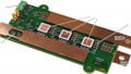
To evaluate the performance of the new shunt-based module, a thermal test under application conditions was performed. The devices under test are the IFF600B12ME4P_B11 modules. Both are without gel and painted black for the evaluation of the internal temperatures using an infrared camera. Additionally, thermocouples are placed in the heatsink below the middle IGBT of the upper system and below the middle shunt. The operation conditions and the temperature of the shunt, IGBT, heatsink, and ambient are depicted in figure 3.

Figure 3: Operation conditions and temperature of the shunt, IGBT, heat-sink, and ambient at maximum operation point for the shunt.
At an output current of 390 A, the shunt achieved the maximum allowed temperature of 200°C. At this operation point, the IGBT junction temperature is at 144°C, very close to its own maximum allowed temperature. It can be concluded that the dimensioning of IGBT and shunt is well-balanced. The difference between NTC and heatsink temperature below the shunt can be more than 20 K and is dependent on the heatsink and operating conditions. It is recommended to perform such a type of test during the inverter design phase to find out the correct temperature conditions for calculation of the shunt temperature. Using the example of figure 3, the shunt temperature can be calculated as follows:

The calculation of the shunt temperature is very close to the measured value.
Summary
The advantages of using shunt resistors integrated into the power module instead of Hall-effect sensors for inverters, at power ranges higher than 75 kW, is presented. The economic and technical benefits are described in detail. The inverter costs can be reduced by 20 € compared to a system with open-loop Hall-effect sensors, and by 50 € compared with closed-loop Hall-effect sensors. The system reliability with the new solution will be increased due to the lower quantity of components, cables and connectors, and improved EMI robustness. The electrical and thermal performance in a real application is explained.
References
- K. Vogel et al., System Cost Reduction with Integration of Shunts in Power Modules in the Power Range above 75 kW, PCIM 2018
- Mouser Electronics, “Texas Instruments AMC1303x High-Precision Delta-Sigma Modulators” https://www.mouser.it/new/Texas-Instruments/ti-amc1303-modulators/
- U. Schwarzer et al., „IGBT Module with integrated Current Measurement Unit using Sigma-Delta Conversion for direct Digital Motor Control“, PCIM 2010
- LEM Holding SA, Datasheet of Current Transducer HTFS 200...800-P, www.lem.com
About the Author
Klaus Vogel is a Technical Marketing Manager at Infineon Technologies for more than 5 years. He studied at Eduard-Spranger-Berufskolleg Hamm and he is a certified Electrotechnical Assistant and pursued Electrical Power Engineering and Environmental Engineering at University of Applied Sciences and Arts Dortmund.
Michael Gadermann is a Technical Marketing Manager at Infineon Technologies for more than five years. He is responsible for the technical support of the EconoPACK™+ and EconoDUAL™3 product family. Michael holds a Bachelor of Engineering in Electrical Engineering from the University of Applied Sciences Soest, Germany. In his former role as Application Engineer he has gained a lot of experience in application support as responsible for Industrial Drives.
Dr. Christoph Urban is a Physicist from Paderborn University and is also awarded with Dr. rer. nat. at RWTH Aachen. He specializes in project management and semiconductors. He currently works as the Project Manager for R&D at Infineon Technologies AG since March 2010.
Andreas Schmal works at Infineon Technologies AG.
This article originally appeared in the Bodo’s Power Systems magazine.
Related Content