Facebook
 Google
 GitHub
 Linkedin
Electrifying Aerospace With Integrated Actuation
Aircraft have used hydraulic actuators to maneuver, but electrification is driving aerospace in the transition from hydraulic actuators to power electronics drives to reduce weight, complexity, and maintenance requirements while improving reliability.
This article is published by EEPower as part of an exclusive digital content partnership with Bodo’s Power Systems.
Traditionally, aircraft have used hydraulic actuators to maneuver, but electrification is driving aerospace in the transition from hydraulic actuators to power electronics drives, reducing weight, complexity, and maintenance requirements while improving reliability.
Airplanes have several flight controls that help them to maneuver on land and in the air. An airplane rotates in bank, pitch, and yaw while also moving horizontally, vertically, and laterally. The four fundamentals (straight-and-level flight, turns, climbs, and descents) are the principal maneuvers controlling the airplane through the six flight motions. On land, the rudder taxis the aircraft left, right, or straight. Both primary and secondary flight controls are used in the air. Primary flight controls consist of a rudder to control the yaw along the vertical axis, an elevator to control the pitch up and down along the lateral axis, and an aileron to control the bank or to turn the airplane along the longitudinal axis, which coordinates rudder and elevator as necessary.
Secondary slight controls consist of trim, flaps, and spoilers. Trim control surfaces are required to offset any constant flight control pressure inputs provided by the pilot. Pitching moments may also be generated by extending and retracting flaps, landing gear, and other drag-producing devices, such as spoilers. Primary flight controls are necessary, while secondary flight controls enhance the plane’s motion in the air with finer control.

Figure 1. Primary Flight controls from FAA Airplane Flying Handbook. Image used courtesy of Bodo’s Power Systems [PDF]
The flight controls get active as the plane gains speed and encounters much force. Pneumatic actuators were used in the early 20th century to move these surfaces. Around the 1930s, aircraft started using hydraulic actuators. These hydraulic actuators consist of a centralized hydraulic reservoir, filters, pumps, and incompressible liquid to move the actuators with the aircraft engine directly driving the hydraulic pumps. These actuators eventually moved to electro-hydraulic actuators that maintained the centralized hydraulic fluid reservoir, while electric motors were used to drive the centralized hydraulic pumps. Most of the old-generation aircraft in service use this technology. The key issues with this central hydraulic system are maintenance, plumbing, frequent filter changes, higher weight, bulkier systems, and higher energy consumption.
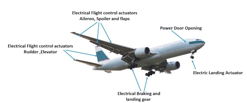
Figure 2. Airplane Actuation Applications. Image used courtesy of Bodo’s Power Systems [PDF]
Actuation Technology
With the invention of actuation technology, there has been a transition from traditional hydraulic systems (EH) to electrohydrostatic actuators (EHA), electrical backup hydraulic actuators (EBHA), and electromechanical actuators (EMA). These actuators replace the central hydraulic system with fly-by-wire to reduce system weight, power consumption, complexity, and maintenance while improving reliability.
Electrohydrostatic actuation (EHA) system eliminates the need for central hydraulic systems. These systems use electric power for aircraft flight control-surface actuation, resulting in reduced aircraft weight, efficient power consumption, and improved maintainability.
EHA systems are power-by-wire actuation systems that utilize aircraft electric power for flight control surface actuation. These systems are highly energy efficient and provide an overall weight benefit to the aircraft. EHA technology is a power-on-demand actuation that reduces overall aircraft power consumption. EHAs improve maintainability since there are no hydraulic connections between actuation equipment and the vehicle system. EHAs consist of a fixed displacement, high-speed, reversible pump driven by a brushless DC electric motor. The pump rotation direction controls the actuator position, and the pump rotational speed controls the actuator piston velocity. The actuator output force is a function of the electric motor output torque.
Electrical backup hydraulic actuation (EBHA) systems are similar to EHA systems but provide backup for the central hydraulic systems with similar advantages.
Electromechanical actuation (EMA) systems are power wire systems that eliminate the need for central hydraulic systems and any sort of hydraulic elements because they use mechanical actuators. An electric motor is dedicated and located at each mechanical actuator on the aircraft. These actuators remove the use of pumps and instead use mechanical gearboxes or similar arrangements powered by an electric motor. This mechanical gearbox drives rotary-to-liner conversion to move the flight controls.
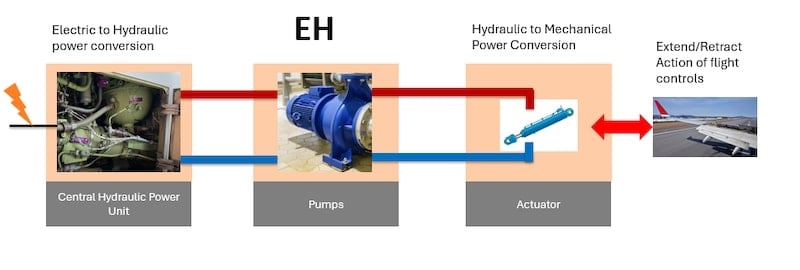
Image used courtesy of Bodo’s Power Systems [PDF]
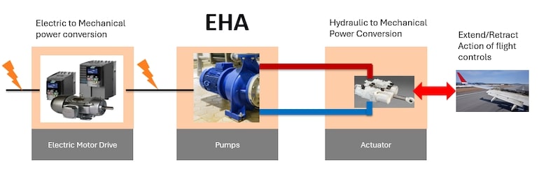
Image used courtesy of Bodo’s Power Systems [PDF]
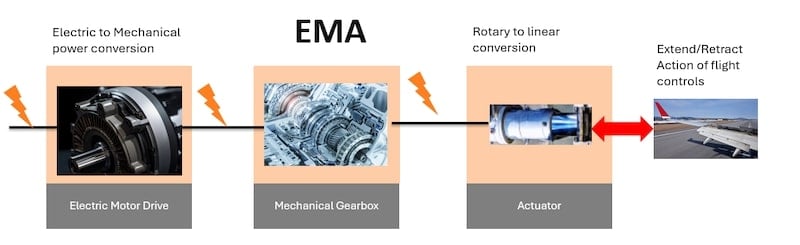
Figure 3. Types of actuators: transition to EHA and EMA is the first step in decarbonization. Image used courtesy of Bodo’s Power Systems [PDF]
The key benefits of this transition from centralized hydraulics systems to EHA/EBHA and EMA include significant weight savings, increased performance, enhanced safety due to improved reliability in demanding conditions, reduced maintenance costs, and lower operating life cycle costs. All these factors together reduce the airplane’s carbon footprint. The bigger the aircraft, the more significant the benefits.
As aircraft evolve to More Electric Aircraft (MEA) and eventually fully electric aircraft, actuation systems will be among the first systems likely to get electrified. This gives us the opportunity to provide solutions for applications including, but not limited to, commercial, cargo, and smaller training aircraft, in addition to the defense sector, Electrical Vertical Takeoff and Landing (eVTOL), drones, and multi-copters.
Figure 4 shows an example of MEA needing power electronics solutions for 24 flight controls, five landing gear, ten fuel pumps, and eight doors. This demonstrates the need for power solutions that enable the change towards decarbonization.
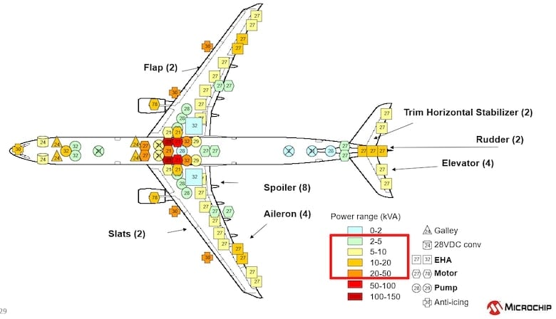
Figure 4. Opportunities in MEA. Image used courtesy of Bodo’s Power Systems [PDF]
Multiple growth drivers enable the demand for actuation electrification:
- Electrification of commercial and cargo airplanes
- Growth in passenger traffic
- Fleet modernization
- Electrification of military and defense airplanes
- Fully electric/H2/hybrid smaller aircraft
- EVTOL for public and cargo transfer
- Drones and multi-copter usage for service and agriculture
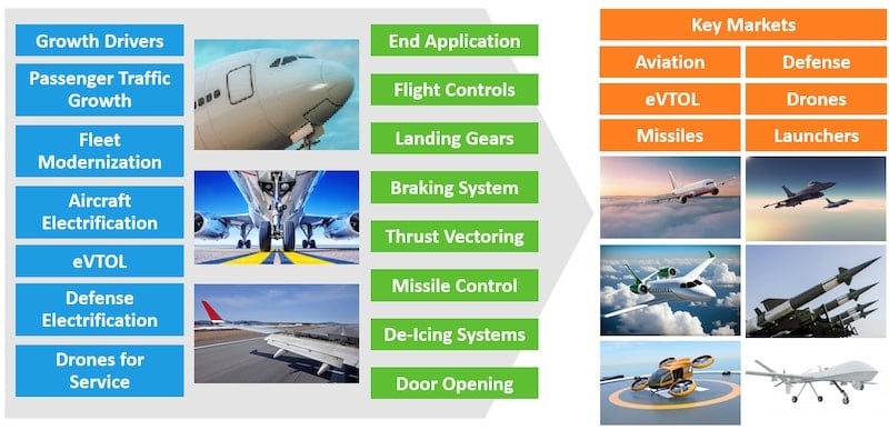
Figure 5. Market segments and growth drivers. Image used courtesy of Bodo’s Power Systems [PDF]
Some key forecasts and analyses from the commercial aviation market reinforce the potential for an expanding electric actuation market.
Fleet modernization: Airlines will require the latest, most efficient, and lowest-emission aircraft. As of 2022, only 25% of the commercial fleet has been electrified.
Passenger traffic: Passenger traffic is expected to grow 3.6% from 2019 to 2041 and will increase the number of aircraft to satisfy this demand.
New generation planes: By 2041, the latest generation of airplanes will represent more than 95% of the fleet. The demand will likely be higher since these planes will use electrical actuation instead of hydraulic. Compared to 2021, only 20% of the fleet represented new planes.
In summary, there will be a demand for more than 40,000 new airplanes by 2042, considering both growth (>23,000) and replacement (>17,000).
To enable this transition, the capability to integrate different electronic power components for functions like power control motion is needed, as well as to provide reconfigurability, standardization, modularity, and reliability to meet aerospace standards.
Power Modules
The actuator generates a translational motion in the forward and reverse direction, converted into rotational motion for flight controls. We need several capabilities to replace the traditional hydraulic system with power electronics. The configurations could be mandatory or optional, depending on the nature of flight control.

1. Motor drive to control the rotational motion of flight control. Image used courtesy of Bodo’s Power Systems [PDF]
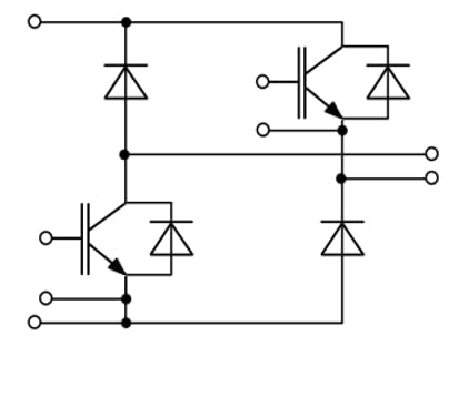
2. Solenoid drive to hold the flight control at the desired position. This feature is important for flight controls that need to be held, such as flaps. Image used courtesy of Bodo’s Power Systems [PDF]
3. Brake chopper to limit DC bus voltage due to regeneration from the motor, allowing energy to freewheel via external braking resistor. Image used courtesy of Bodo’s Power Systems [PDF]
4. Soft starter to control the inrush current at the start of the motor; this is achieved by a soft start switch. Image used courtesy of Bodo’s Power Systems [PDF]
Figure 6. Integration of multiple topologies in one compact power module.
The power range of the typical actuator ranges up to 25 kW for an operating pressure of 5000 Psig with a stroke length of 10 inches. These ratings vary depending on the application, but they provide a generic rating that is commonplace in the aviation industry. The DC link voltages are primarily 270 V and 540 V. The electric motor switching frequency varies between ~2 to 10 kHz. Due to the higher voltage involved, it is important to have a fully isolated module with enhanced thermal capabilities to provide low power loss and high efficiency to enable smaller weight and footprints. It is essential to have 650 V to 700 V power modules for 270 V DC link and 1200 V for 540 V with the ability to provide derivatives up to 1700 V if required.
Hybrid SiC (IGBT + SiC D) and SiC are recommended to provide optionality to the customer. For relatively high frequency, full SiC, including SiC MOSFETs and Schottky diodes, helps to reduce switching losses, while hybrid SiC balances the benefits versus cost when the Fsw is relatively lower. The low junction-to-case thermal resistance and Silicon Nitride (Si3N4) substrate improves the thermal performance of the module. Using an Aluminum-Silicon Carbide (AlSiC) baseplate further reduces the weight while extending the solution’s reliability. This results in high power density, which helps shrink the solution’s size and weight, allowing greater power density in the given area. This is a critical differentiator in aerospace applications. Lower thermal losses reduce the cooling requirements and improve the overall efficiency of the converter, impacting the power consumption positively.
The Integrated Actuation Power Modules need to have very low package inductance. The current change rate (di/dt) could be substantially higher due to high switching frequency (Fsw). This high di/dt with higher stray inductance results in higher overall inductance and higher voltage overshot during the switch turn-off. [V overshoot = V & L di/dt]. Having a lower overshoot improves the ruggedness of the power module.
It is also important to have temperature monitoring that can be easily implemented to control temperature conditions and improve protection. Monitoring the DC bus, inverter, and solenoid current with feedback to control circuity enhances the durability of the power module.
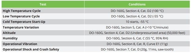
Figure 7. Qualification test plan. Image used courtesy of Bodo’s Power Systems [PDF]
To comply with the high standards of aviation, qualification as per DO-160G for flight conditions like Low/High-temperature cycling, cold start-up, altitude of 50,000 feet, cold temperature -55 Deg C, humidity, shocks, and vibrations), highly accelerated life testing (HALT), RoHS, partial discharge test and AS9100 adherence are key.
While most engineers can design their own driving circuitry compatible with the power module, having a fully integrated solution for actuation provides an all-in-one solution, minimizing the design efforts and costs associated with projects. This accelerates time to market, complexity, and the lack of flexibility associated with system design for MEA actuation.
The gate driver board should provide the PWM signal to the power module based on the inputs from the higher-level system. This may include all the inverter switches, solenoid drives, soft starters, and brake switches. Apart from providing the gate signals, the driver should be able to provide isolation and continuous monitoring of the following parameters and provide output to LVDS:
- DC link bus voltage
- DC link bus current
- Phase current output of inverter
- Solenoid current
- Temperature of power module
The driver board should have the voltage across the shunts in the power module and provide current measurement signals as isolated differential output for phase current, bus current, and solenoid current. It should also measure the DC link bus voltage and provide an isolated differential voltage output.
In normal operation, the driver board would receive PWM switching signal inputs from a higher–level system and provide the gate–drive signals to the power module to control the functioning of the three-phase inverter bridge switch, solenoid switch, soft–start switch, and brake switch.
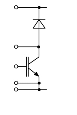
Microchip’s Integrated Actuation Solution
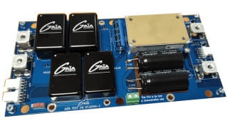
Microchip’s cost-effective, plug-and-play Integrated Actuation Power Solution combines a Hybrid Power Drive (HPD) and a compatible driver board that provides intelligence, scalability, design flexibility, reliability, faster time-to-market and high-power density for aircraft power system applications in MEA, cargo planes, small planes, defense avionics, eVTOL aircraft, drones, and multicoppers. The HPD modules range from 5 kVA to 20 kVA and have the same footprint. These modules include a three-phase inverter with temperature and output current measurements and options for a brake chopper, solenoid drive, and soft starter. They can be configured with Silicon (Si) or Silicon Carbide (SiC) switches. The isolated gate driver board can manage the intricacies of driving MOSFETs and Insulated-Gate Bipolar Transistors (IGBTs) at a higher switching frequency. The press-fit connector enables the board to be attached easily to the top of the HPD module in accordance with DO-160 and AS9100 standards for the aerospace industry. You can also order an HPD module and a driver PCB assembly separately for design freedom and adaptability.
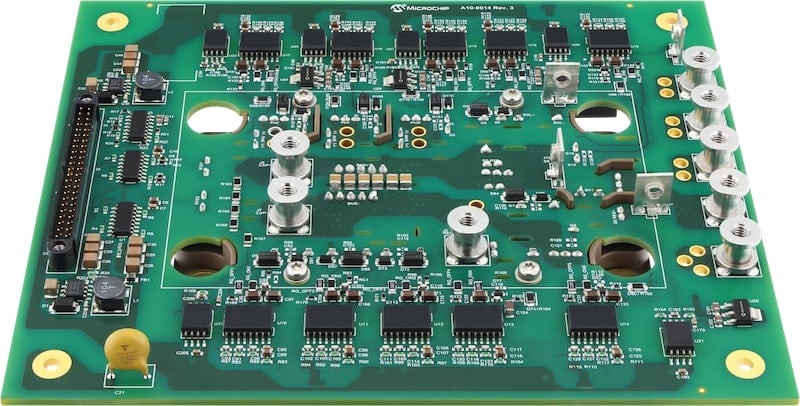
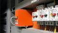
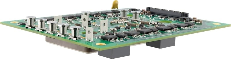
Companion Driver Board Image used courtesy of Bodo’s Power Systems [PDF]
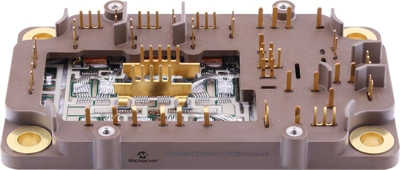
Power SP6HPD Module Image used courtesy of Bodo’s Power Systems [PDF]
Integrated Actuation Solution. Image used courtesy of Bodo’s Power Systems [PDF]
Figure 8. Integrated Actuation Power Solution.
Some key benefits include:
- High level of integration and flexibility -Includes inverter, brake chopper, solenoid drive, soft starter, thermal sensors, telemetry outputs, and gate driver board
- Modular and adaptable SiC/IGBT solution with nominal DC link up to 540 VDC and power rating up to 20 kVA
- Isolated gate drive board with shoot-through detection, multiple protections, and high-speed Low-Voltage Differential Signaling (LVDS)
- Cost-effective, high-reliability, and rugged solution
- High power density with reduced weight, smaller footprint, optimized design, and efficient semiconductors
- Faster time to market -Easy-to-use modular design with integrated functionality reduces the number of components and testing requirements
- Flight-proven standard and custom solutions available up to 1700 V
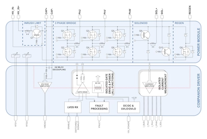
Figure 9. Block diagram of the Integrated Actuation Power Solution. Image used courtesy of Bodo’s Power Systems [PDF]
This article originally appeared in Bodo’s Power Systems [PDF] magazine.