Facebook
 Google
 GitHub
 Linkedin
Bipolar Power Module Packaging Improvements
Bipolar modules remain a robust and cost-effective solution for industrial line-frequency applications. While the basic operation of such circuits has not changed, the packaging technology in the power modules continues to improve.
This article is published by EEPower as part of an exclusive digital content partnership with Bodo’s Power Systems.
Bipolar modules remain a robust and cost-effective solution for industrial line-frequency applications. While the basic operation of such circuits has not changed, the packaging technology in the power modules continues to improve. Since its invention in 1975, the SEMIPACK isolated baseplate rectifier module has grown into an extensive product line covering many currents and topologies. It has become the standard in 50/60Hz rectifiers and AC controllers and is widespread in markets such as motor drives, UPS systems, and process control.
The SEMIPACK product line (Figure 1) now covers six different housings containing diodes and/or thyristors with nominal current ratings from 60A (SEMIPACK 1) to beyond 1300A (SEMIPACK 6). These modules are configured for uncontrolled (diode/diode), half-controlled (thyristor/diode), and fully controlled (thyristor/ thyristor) rectification. Thyristor/thyristor modules are also easily configurable for AC control (anti-parallel connection). Construction of these modules varies across the range. Lower power modules have wire-bonded and soldered connections and larger types have a pressure construction similar to capsule devices.
Each of the six housing sizes has gone through individual revisions. The original type, SEMIPACK 1, has undergone five generational changes to maintain its position as the market leader. Now, the 6th generation, SEMIPACK 1.6, is available with the full range of current ratings. This brings the highest performance and current capability to all bipolar applications.
Module Construction
The SEMIPACK 1 module utilizes the well-established construction of a lead frame, chip-on-substrate, and baseplate. The use of a copper baseplate in these 20mm-wide modules improves thermal spreading as well as provides a robust mounting surface across different heatsink types. For the 6th generation SEMIPACK 1, the internal construction has been changed. These changes improve thermal performance and reduce materials, significantly improving the cost/performance ratio.
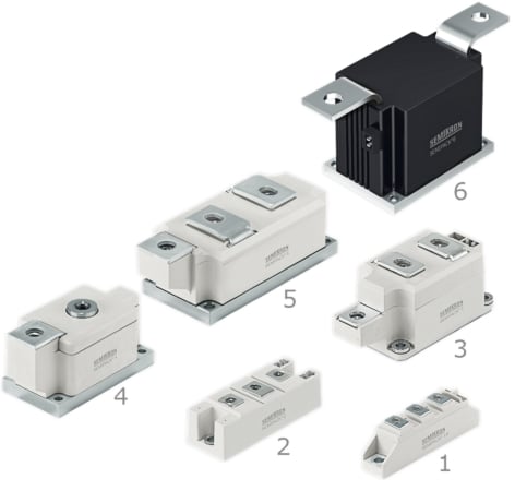
Figure 1. SEMIPACK Family. Image used courtesy of Bodo’s Power Systems [PDF]

Figure 2. Comparison of internal construction. Image used courtesy of Bodo’s Power Systems [PDF]
First, the material stack-up beneath the bipolar semiconductor chip has been drastically simplified (Figure 2, top). This greatly reduces the thermal resistance from chip to baseplate (Rth(j-c)). The SEMIPACK 1.6 exhibits a 46% reduction in steady-state thermal resistance from semiconductor junction to case over the previous generation (Figure 2, bottom).
Second, the baseplate in the SEMIPACK 1.6 has been reduced in size. Obviously, this conserves valuable copper, with a total weight reduction of the module from 95g to 75g (-18%). But in previous SEMIPACK generations, this baseplate also had screw holes and provided mounting pressure to hold the module to the heatsink. This required a complex bend in the baseplate to ensure uniform contact with the heatsink after mounting. In the “hybrid” design of the SEMIPACK 1.6, the reinforced plastic housing encases the baseplate and provides mounting pressure. This allows for much simpler baseplate geometry to greatly increase the effective contact area to the heatsink underneath the chips. The improved metal-to-metal contact area between the baseplate and heatsink also means less thermal interface material is required. The SEMIPACK 1.6 reduces the overall case-to-sink thermal resistance, Rth(c-s), by 35% (Figure 3) over the previous generation, with a typical value of 0.09K/W.

Figure 3. Comparison of external construction. Image used courtesy of Bodo’s Power Systems [PDF]
Despite these changes to the construction, the external dimensions, mounting locations, and electrical terminals all remain the same as in previous SEMIPACK 1 generations. This means that existing mechanical designs can benefit from higher performance. As an industry-standard package, the SEMIPACK can replace outdated rectifiers in the same footprint.
Application Performance
The improved thermal performance of the 6th generation is clear when looking at the resulting semiconductor junction temperature during operation in a typical electrical circuit. One of the most common industrial circuits is the line-fed, 3-phase bridge rectifier. This is easily constructed with three SEMIPACK 1 modules on a single heatsink. The input to the bridge is typical line voltage (e.g., 400VAC, 50Hz), with the DC output being filtered to provide current to a typical load (e.g., inverter). Such a circuit can be easily simulated using the online SemiSel simulation tool, accessible through the Semikron Danfoss website. This free-to-use tool includes models of all the SEMIPACK types and quickly gives the semiconductor junction temperature for a given set of conditions. For this example, the three SEMIPACK modules on a heatsink are forced-air cooled with 45°C inlet air. If it is assumed that the inverter on the output of the rectifier is driving a motor, then it is typical to consider a 3s, 180% overload as well.
With these conditions in mind, the dual-diode (SKKD) SEMIPACKs of the 5th and 6th generations can be compared (Figure 4). Each 5th generation SEMIPACK 1 is first simulated with the rectifier bridge output current that results in the junction temperature reaching the recommended operating limit during an overload condition. As is common for design across the industry, this recommended operating temperature limit is 10°C below the maximum junction temperature listed on the datasheet.
For example, the SKKD 81 (5th generation) nearly reaches the recommended operating limit (115°C) when the output current of the 3-phase rectifier is 207ADC (3s overload condition). However, under the same operating conditions and output current, the equivalent 6th generation device (SKKD 95) only reaches a junction temperature of 103°C. Furthermore, the release of the 6th generation of SEMIPACK has allowed qualifying the devices to a maximum junction temperature, Tj,max, of 130°C. This represents a 5°C increase over nearly all the devices in the 5th generation. With the previously mentioned 10°C operating margin applied, this means that 6th generation devices are capable of operating continuously up to 120°C.

Figure 4. SEMIPACK 1.5 vs. 1.6 (diode/diode configuration). Image used courtesy of Bodo’s Power Systems [PDF]
Portfolio
The new SEMIPACK 1.6 portfolio (Figure 5) covers the existing current range of the 5th generation while expanding the upper current limit. The improved design allows for an IFAV = 143A at Tc = 85°C for the dual-diode equipped packages. In the case of the thyristor-equipped packages (SKKH and SKKT), the current rating of ITAV = 145A at Tc = 85°C is the highest current rating on the market for 20mm packages. The surge current capability is also best in class, with ITSM = 2210A @ Tj = 130°C.
Given the widespread use of 400/480V networks, all SEMIPACK 1.6 have a reverse blocking voltage of 1600V. However, 1800V devices will also be offered.

Figure 5. SEMIPACK 1.6 Portfolio. Image used courtesy of Bodo’s Power Systems [PDF]
Summary
The 6th generation SEMIPACK 1 continues the tradition of innovation started with the original isolated power semiconductor module. By utilizing fewer materials, SEMIPACK 1.6 contributes to efforts to improve sustainability in the electronics industry while simultaneously improving thermal performance. With each new SEMIPACK generation, the cost/performance ratio improves, ensuring it remains the rectifier module of choice for all industrial applications.
This article originally appeared in Bodo’s Power Systems [PDF] magazine.
Related Content