 Facebook
 Google
 GitHub
 Linkedin
Basic DC Circuit Theory
Voltage, Current, Energy, and Power
Voltage and Current Relationship
The earth is a dynamic place. Objects are moving, chemical reactions are taking place, temperatures are increasing and decreasing. This abundance of perpetual activity is bound to the concept of energy. The various forms of energy—thermal, mechanical, chemical, etc.—are manifestations of a fundamental entity that results in physical change as it is transferred from one object to another.
Electricity is a form of energy that results from the existence and movement of charged particles called electrons. When the accumulation of electrons creates a difference in electric potential energy between two points, we have a voltage (in equations, voltage is denoted by V). If these two points are connected by a conductive material, electrons will naturally move from the lower voltage to the higher voltage; this movement is called electric current, denoted by I.
Electricity is a particularly convenient and versatile form of energy, and this has made it a powerful tool in the hands of the countless clever individuals who have designed everything from large electrical equipment to tiny electronic devices. It is astonishing to think of the diverse and sophisticated functionality that begins with electrical energy that can be transferred through two small copper wires.
Voltage and Current Comparison
| Current | Voltage | |
| Symbol | I | V |
| Relationship | Current cannot flow without Voltage | Voltage can exist without current |
| Measured with | Ammeter | Voltmeter |
| Unit | A or amps or amperage | V or volts or voltage |
| SI Unit | 1 ampere =1 coulomb/second | 1 volt = 1 joule/coulomb (V=W/C) |
| Field | Magnetic | Electrostatic |
| In Series Connection | Current is the same through all | Voltage is distributed over components |
| In Parallel Connection | Current gets distributed over components | Voltages are the same across all components |
Power in Electronics and How its Calculated
In a scientific context, power refers to the rate at which energy is transferred. Electrical power, then, is the rate at which electrical energy is transferred. The unit is watts (W), where one watt is equal to the transfer of one joule (J) of energy in one second (s).
`1\ W=1\ \frac{J}{s}`
Electric power in watts is equal to voltage in volts multiplied by current in amperes.
`\text{power}=\text{voltage}\ \times \text{current}`
The unit volts (V) is defined as joules per coulomb, i.e., it conveys energy (in joules) per coulomb of charge. The ampere (A) is coulombs per second, i.e., how many coulombs of charge pass a given point in one second. We can use this information to confirm that the unit for electrical power is consistent with the formula given above:
`\frac{\text{joules}}{\text{second}}= \frac{\text{joules}}{\text{coulomb}}\times\frac{\text{coulombs}}{\text{second}}`
On the right side of the equation, the two “coulomb” terms cancel out, and we are left with joules per second.
When we are analyzing circuits, we typically discuss power using the term “dissipated” or “consumed” instead of “transferred.” This emphasizes the fact that the power leaves the electrical system or is used by an electrical component. We don’t say “transferred” because, in general, the final state or location of the energy is not important.
For example, if the voltage across a resistor is 5 V and the current through the resistor is 0.5 A, the resistor is transferring 2.5 W of power (as heat) to the surrounding environment. However, in most cases, we are not intending to transfer energy. We simply want to design a functional circuit, and consequently, we think in terms of how much power is lost (i.e., dissipated) or used (i.e., consumed).
Two Common Types of Voltage: Direct and Alternating Current
There are two common ways of transferring electrical energy: direct current and alternating current.
Direct current (DC) can increase or decrease in all sorts of ways, but the magnitude of the changes is usually small with respect to the average value. The most fundamental characteristic of direct current, though, is the following: it does not regularly change direction. This is in contrast to alternating current (AC), which regularly changes direction and is used all over the world for the distribution of electrical power.
The terms “DC” and “AC” have become adjectives that are frequently used to describe a voltage. This can be a bit confusing at first: what is a direct-current voltage or an alternating-current voltage? This is not the best terminology, but it is completely standard. A DC voltage is a voltage that produces, or would produce, DC current, and an AC voltage produces or would produce AC current—and this introduces another terminology problem. “DC” and “AC” are sometimes attached to the word “current,” even though these phrases mean “direct-current current” and “alternating-current current.” The bottom line is that “DC” and “AC” are no longer exact equivalents for “direct current” and “alternating current”; DC refers in a general way to quantities that don’t regularly change polarity or that have very low frequency, and AC refers in a general way to quantities that regularly change polarity at a frequency that is not “very low” in the context of a given system.
For now, we’ll focus on DC circuits. AC circuits are a bit more complicated and will be discussed later in this chapter.
Voltage Symbols
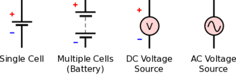
What is DC Voltage?
Perhaps the most familiar source of DC voltage is a battery. A battery is a device that converts chemical energy into electrical energy; it provides a voltage that doesn’t change rapidly or reverse polarity, but the voltage gradually decreases as the battery is discharged.
A DC voltage can be measured using a voltmeter or (more commonly) a multifunction device known as a multimeter (abbreviated DMM, where the D stands for “digital”). Multimeters can measure, among other things, voltage, current, and resistance.

Figure 1. A voltage measurement shown on the digital display of a multimeter.
A voltmeter provides the simplest way to determine the exact value of a DC voltage, though in some cases it fails to convey important information because it cannot clearly display rapid variations. This is an important consideration nowadays because many DC voltages are generated by switching regulators that result in high-frequency variations called ripple.
What is DC Current?
When a DC voltage is present between two terminals and a wire or resistive element is connected to the terminals, DC current will flow. The most common resistive element is the resistor; we’ll learn more about this component in the next page. An incandescent light bulb is also a resistive element.
Current can be measured using a device called an ammeter (or the ammeter functionality of a multimeter), but measuring current is less convenient than measuring voltage. The probes of a voltmeter are simply placed in contact with two conductive surfaces (i.e., without modifying the circuit), whereas the probes of an ammeter must be inserted into the current path:

Figure 2. This circuit uses a switch to establish a current path during normal operation and break the current path when an ammeter or DMM must be inserted.
Conventional Current Flow Vs. Electron Flow
It is very important to understand the difference between conventional current flow and electron flow. Electrons have a negative charge, and consequently, they move from lower voltage to higher voltage. In Figure 2, however, the arrow indicates that current is flowing from the positive battery terminal to the negative battery terminal—in other words, from higher voltage to lower voltage.
Conventional current was originally based on the assumption that electricity is associated with the movement of positively charged particles. We now know that this is incorrect, but in the context of circuit analysis, the conventional-current-flow model is not incorrect. It is perfectly valid because when applied consistently it always produces accurate results. Furthermore, it has the advantage of creating the intuitive situation in which current flows from higher voltage to lower voltage, just as fluid flows from higher pressure to lower pressure and water falls from higher elevation to lower elevation.
In the world of electrical engineering, circuits are discussed and analyzed using conventional current, not electron current.
How to Measure DC Current
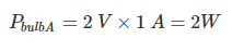
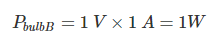
Let’s look at the simple case of a battery powering two light bulbs of unequal resistance.

Figure 3. A basic circuit consisting of a 3V battery and two resistive elements.
When current is flowing through the light bulb, the resistance of the filament causes a loss of voltage that is proportional to the resistance and the amount of current. We refer to this as the voltage across the bulb or as the bulb’s voltage drop.

Figure 4. Voltmeters are used to measure the voltage across the light bulbs.
We see that the voltage across light bulb A is 2V and the voltage across light bulb B is 1V.
Next, we’ll measure the current.

Figure 5. An ammeter is inserted such that the current flowing through the light bulbs flows into one probe, through the device’s current-measuring circuitry, and out the other probe.
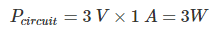
Let’s assume that we measure 1A. We have now made the measurements that we need in order to determine the power dissipation of the light bulbs.
DC Power Calculation
To calculate the power dissipated by each light bulb, we insert the measured values into the formula given above.
If we want to know the power dissipated by the entire circuit, we add up the power dissipation of the individual components:
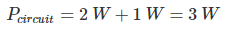
Or, we can multiply the current supplied from the battery by the battery’s voltage:
Stay tuned, because on the next page we’ll introduce Ohm’s law, which expresses the fundamental relationship between current, voltage, and resistance.
excellent basic explanation