Facebook
 Google
 GitHub
 Linkedin
Power Supply Cost Analysis: Discrete, Modular, Complete
Engineers must make many decisions about power supplies. This article examines several factors to consider.
This article is published by EEPower as part of an exclusive digital content partnership with Bodo’s Power Systems.
One important element in achieving the desired system performance is the selection of the optimal power supply solution. Developers can choose from a wide range of options, be it their own discrete design, a modular approach by using DC/DC modules and a few external components or a complete, off-the-shelf solution. Due to the large number of converters and power supplies available on the market, solutions can be found in most cases and the demand for semi-custom or fully customized designs is decreasing.
A general rule of thumb is that 5 to 10% of the total material costs of a system are spent on the power supply. In a cost analysis, the components for a discrete power supply appear to be small items among the general components, while DC/DC converters or complete power supplies are always at the top of the list. Does this mean that a discrete solution is always the most cost-effective? This article will look at the pros and cons of each solution and why, in most cases, a modular or complete solution approach is more cost-effective.
Discrete Design
The highest degree of flexibility is achieved by developing fully customized solutions, and a wide variety of controller chips and transformers for different topologies are available, along with reference designs.
At first glance, developing a power solution does not appear to be too difficult and, to a certain extent, is true for non-isolated, low-power converters. However, designing higher power or isolated converters becomes a real challenge as it requires in-depth knowledge of power electronics, high-frequency switching, thermal management, EMC behavior, and safety approvals. Many companies no longer have the necessary know-how and resources in their development departments.
The entire design process, including the qualification tests and safety plus EMI approvals, can take months and generate high total NRE costs. Even a minor change in the specifications may require a complete redesign. Discrete solutions are viable options for devices where the lowest component costs are essential, and the significant development cost can be amortized over large quantities.
Modular Solution
More and more designers are opting for solutions based on DC/ DC converter modules. The modular approach does not require in-depth knowledge of power electronics and allows very flexible designs while saving time and money on development and safety approvals. The design can be completed in a few weeks or even days, and last-minute changes can often be implemented quickly by simply changing or adding a module. Safety approvals and EMC compliance are greatly simplified because the modules have worldwide approvals, meet market-specific standards, and have built-in filters and protection circuits. For design, approvals, and specific EMI requirements, manufacturers provide comprehensive sets of documentation together with easy-to-implement reference designs (Figure 1).

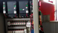
Figure 1. P-DUKE’s comprehensive literature offering makes design of modular solutions easier. Image used courtesy of Bodo’s Power Systems [PDF]
In the railway market the modular approach is quite often used as it enables high flexibility at low total cost, and the modules are qualified for the extreme environmental conditions in rolling stock applications. In this example, an isolated ±5 V/5 W supply voltage was needed, to be generated from the different nominal voltages on trains. Solution also had to comply with various railway standards. The system is sold in quantities of 100-300 units on a projectby-project basis with annual total quantities below 1500 systems. These volumes don’t justify the high cost for own discrete designs. They call for a modular solution. One big challenge is the number of nominal voltages in train applications (Figure 2).

Figure 2. Different nominal voltages in trains with corresponding tolerances. Image used courtesy of Bodo’s Power Systems [PDF]
Considering all nominal voltages and their tolerances, the supply voltages span from 14 V up to 160 V. Converters covering this full range are available but to keep the size of a DC/DC module family as small as possible, many manufacturers split the voltages into two ranges (9-75 V and 14-160 V) or three ranges (9–36 V, 18–75 V and 40–160 V). Quite often systems are produced for a specific train project with fixed voltages, and the appropriate converter can be mounted on the PCB.
The RDL06 from P-DUKE was selected as it delivers up to 6 W power in a SIP-8 package measuring 21.8 mm x 9.6 mm x 11.2 mm while providing the necessary safety approvals and isolation voltages. Towards the end of the design phase power requirements increased to 8.5 W, but the design engineers were able to use the 10 W version of the converter in the same package. It was a plug and play solution, not requiring any PCB layout change (Figure 3).

Figure 3. P-DUKE’s RDL series offers 3 W, 6 W and 10 W versions in a SIP-8 package. Image used courtesy of Bodo’s Power Systems [PDF]
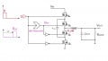
With a few external components the EMI requirements of EN55023 and EN50121-3-2 and the transient requirements of EN61000-4-4 are met. Figure 4 shows the complete circuit based on an application note from P-DUKE. It also includes reverse polarity protection at the input.

Figure 4. EMI, transient and reverse polarity protection realized by a few external components. Image used courtesy of Bodo’s Power Systems [PDF]
The module is internally fully encapsulated with silicone making it extremely resistant to shock and vibration defined in EN61373 and MIL-STD-810F. The potting material also transfers heat from the internal components to the metal housing. P-DUKE was the first manufacturer to introduce separate case pins for these products. It makes the module more resistant to shock and vibration and some of the heat can be dissipated to the PCB board (Figure 5). Furthermore, these modules also offer remote on/off and protection against overcurrent and short circuits.

Figure 5. Additional case pins make the module more robust and allow heat transfer to the PCB. Image used courtesy of Bodo’s Power Systems [PDF]
Time to Market
How many months would it take to realize and approve an adequate discrete solution with 50 or more components? Isn’t it easier to complete a design in a few weeks and buy, store and place only three different DC/DC converters depending on the voltage in a specific train project?
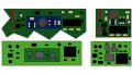
P-DUKE offers one of the largest DC/DC module portfolios worldwide, enabling solutions for different supply voltages and power levels from 1 W up to 300 W not only in the railway but also in medical, industrial or defense markets. Input voltage ranges span from 2:1 up to 12:1, and cooling methods can be convection, forced air, attached heatsinks and cool plates, which enables hermetically sealed and waterproof solutions (Figure 6).

Figure 6. DC/DC modules are available in different form factors. Image used courtesy of Bodo’s Power Systems [PDF]
Modular Approach
The modular approach with DC/DC converters offers a high degree of flexibility but more and more engineers are looking for solutions that can be implemented quickly, without the need for design, test or approval. Complete solutions, which have been standard in many AC/DC applications for years, are becoming increasingly popular in DC/DC applications, too. They incorporate all necessary features and functionality, have worldwide safety approvals, and are plug and play solutions.
Let’s look again at an example in the train market where digitization is constantly progressing. Retrofitting existing systems and adding new features require standard, easy to install power supplies which work from all the different train voltages and can be stored for a fast response. P-DUKE’s URCD family is a total solution that can handle input voltages from 14 VDC up to 160 VDC, provides all standard output voltages with up to 20 W of power, has all relevant rail standards approvals, and can be mounted on a chassis or on DIN rails. Figure 7 shows the block diagram of this solution.
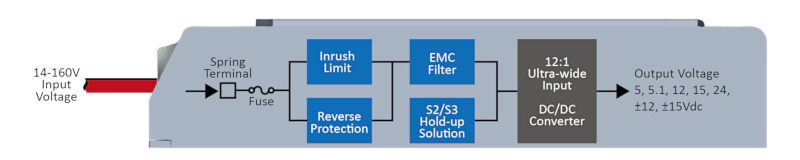
Figure 7. Block diagram of the URDC family, a total solution for railway applications. Image used courtesy of Bodo’s Power Systems [PDF]
Spring Terminals
Spring terminals, which are also called push pins (Figure 8), make electrical connection very easy. Safety standards require a fuse, which is already incorporated into the unit, is limited to 15 A when the unit is switched on, thus preventing any upstream fuses from being tripped (Figure 9).
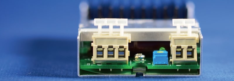
Figure 8. Electrical connections can be made by using spring connectors. Image used courtesy of Bodo’s Power Systems [PDF]
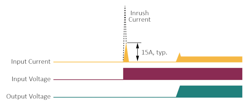
Figure 9. When the unit is switched on, inrush current is limited to 15 A. Image used courtesy of Bodo’s Power Systems [PDF]
Reverse Protection
In the event of an incorrect connection, the built-in reverse polarity protection disconnects the unit from the supply voltage (Figure 10). Unlike simpler reverse polarity protection solutions, no fuse is blown, and therefore, there is no need to replace them in case of an incorrect connection.
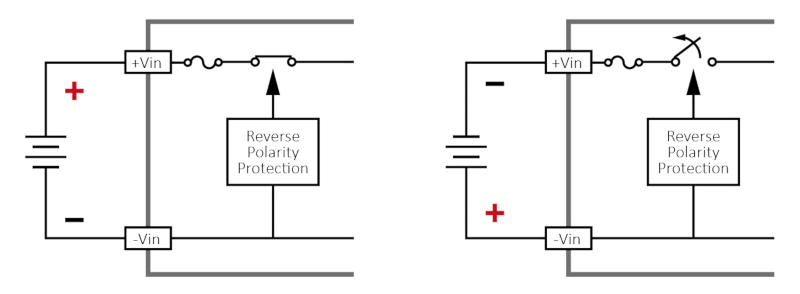
Figure 10. In case of a wrong connection, the device is disconnected from the source. Image used courtesy of Bodo’s Power Systems [PDF]
EMI/EMC
The EMC filter guarantees that EN55032 and EN50121-3-2 Level B and high voltage transient requirements are met. Supply voltages on trains can also have interruptions of 10 ms (S2) or 20 ms (S3), during which the power supply must deliver full power. P-DUKE’s patented hold-up circuit is implemented in some modules for the rail market and charges external hold-up capacitors. In the event of a supply interruption, these capacitors deliver the necessary energy to the DC/DC converter. Figure 11 shows definitions of supply interruptions and the circuit implemented in the URDC family.
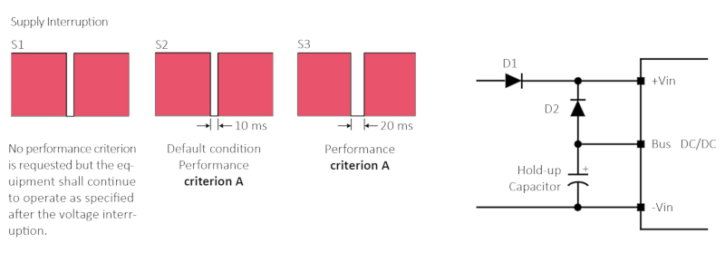
Figure 11. Supply interruption definitions and P-DUKE’s patented solution. Image used courtesy of Bodo’s Power Systems [PDF]
The DC/DC converter works from 14 V up to 160 V covering all standard voltages in railway and rolling stock applications. One single power supply enables the quick installation of a system in any application worldwide.
Total Solution
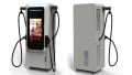
Total solutions don’t require extra time for design, test, qualification and approvals. Data for environmental qualifications are provided by the manufacturer, which also guarantees functionality under all specified conditions. P-DUKE offers a range of complete AC/DC and DC/DC solutions. For the AC/DC market open frame, enclosed and encapsulated solutions with power levels from a few Watts up to 500 W are available (Figure 12). They are all compatible with worldwide mains, have international safety approvals, and many products meet the stringent requirements in medical applications.
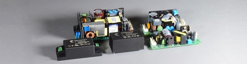
Figure 12. AC/DC total solutions from P-DUKE’s product portfolio. Image used courtesy of Bodo’s Power Systems [PDF]
Besides the URDC Family, P-DUKE offers several total DC/DC solutions for chassis, and DIN rail mounting (Figure 13), with power levels from 15 W up to 300 W, single or dual output voltages from 3.3 V up to 48 V, and various input voltage ranges from 8.5 V up 160 V.
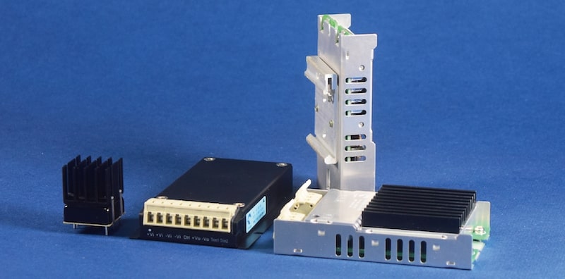
Figure 13. P-Duke offers total DC/DC solutions with different mounting options. Image used courtesy of Bodo’s Power Systems [PDF]
Whatever the solution, whether modular or complete, with the wide range of available products, a suitable, cost-effective power supply can always be found without incurring high costs for development and approval.
This article originally appeared in Bodo’s Power Systems [PDF] magazine.