Facebook
 Google
 GitHub
 Linkedin
Power ICs Enable High-Efficiency High-Power-Density 140W PD3.1 Adapter Designs
This article presents an ultra-high-efficiency and high-power-density design of a power factor correction (PFC) and asymmetrical half-bridge (AHB) flyback converter for 140 W PD3.1 adapter applications. GaNSense power ICs are used in the boost PFC design for higher frequency, smaller inductors, and higher efficiency.
GaNSense half-bridge ICs enable the ZVS AHB flyback topology to operate at higher frequencies with a smaller transformer and higher efficiency. A 140 W PD 3.1 evaluation board is presented that demonstrates the functionality and performance of the complete system design. The evaluation board achieves 94.5% efficiency at 90 VAC and 95.8% at 230 VAC, at least 1% higher efficiency, and up to 20% energy savings vs. prior state-of-the-art designs. The estimated case size is 100 cc for a power density of 1.4 W/cc.
Higher Speed + Higher Efficiency = Smaller Size
The growing demand for size reduction of power supplies has continuously challenged the industry to produce higher and higher efficiencies and power densities. The ability to improve the performance of silicon-based power supplies has slowed due to silicon devices reaching their maximum frequency limit (<100 kHz), which has prevented further optimization of circuit topologies and magnetic design. Emerging GaN wide-bandgap devices have enabled significant incremental efficiency and size improvements due to their 15x lower QG gate charge, 16x lower Qoss output charge, and higher switching speeds. GaNSense power ICs have enabled these devices to finally exit the lab and enter real-world fast chargers and adapters by integrating all the missing ingredients needed for reliable and robust designs. These include integrated gate drive, regulated gate voltage, loss-less current sensing, and protection features in GaNSense power ICs and GaNSense half-bridge ICs (Figure 1). These latest products enable new circuit topologies, and the industry is using them to progress ahead with smaller, more efficient designs.

Figure 1. GaNSense power IC and GaNSense half-bridge IC simplified block diagrams and key features. Image used courtesy of Bodo’s Power Systems [PDF]
GaNSense Boosts PFC Frequency and Efficiency
Power factor correction (PFC) is required for output powers greater than 75 W. The traditional boost PFC converter has dominated due to its simplicity, low harmonic current, and low cost. Many off-the-shelf PFC controllers provide multi-mode CRM or DCM operation to improve system efficiency and line-current harmonics. GaNSense power ICs improve this topology by increasing the switching frequency to reduce the inductor size and increasing efficiency to reduce losses and thermals (Figure 2). The integrated GaN FET allows the frequency to be increased easily due to the lower output charge and gate charge compared to silicon FETs. To increase the efficiency, GaNSense power ICs integrate a loss-less current sensing method that eliminates the external RCS current-sensing resistor and its associated hotspot and footprint.

Figure 2. Si-based boost PFC (left) vs. loss-less GaNSense boost PFC (right). Image used courtesy of Bodo’s Power Systems [PDF]
A boost-follower function can be added to improve efficiency further so that the DC bus operates at a lower voltage during low-line AC input. This gives lower peak-current levels, lower negative current and circulating energy, and lower core losses (Figure 3). All of these improvements combined give an additional +0.3% efficiency benefit.

Figure 3. Boost peak-inductor currents over AC half-cycle at full-load and different DC-bus voltage levels, 90 VAC/400 V (left) and 90 VAC/260 V (right). Image used courtesy of Bodo’s Power Systems [PDF]
GaNSense enables AHB and AHB enables PD 3.1
The quasi-resonant flyback is a popular topology for the downstream converter due to its wide voltage gain capability. However, as power levels increase above 100 W, the transformer leakage energy increases significantly. As the leakage energy increases, the voltage stress on the primary switch and secondary SR switch also increases, including higher voltage spikes and EMI noise. In addition, the USB Power Delivery Specification Revision 3.1 enables higher output-voltage levels, e.g., 28 V to 48 V, which makes the flyback transformer turns ratio more difficult to design. The voltage stress on both primary and secondary is much higher than the traditional 20 V output condition. The asymmetrical half-bridge flyback converter operates with zero-voltage switching (ZVS) of the primary-side switches and zero-current switching (ZCS) of the secondary-side rectifier. Moreover, the primary switches are clamped at the PFC output voltage, typically around 400 V, so the stress and voltage ringing issues are significantly relieved. For these reasons, the AHB topology is the preferred choice for PD 3.1 applications, and GaNSense half-bridge ICs enable high-frequency operation for small transformer sizes and loss-less current sensing for higher efficiency (Figure 4).

Figure 4. Si-based QR flyback (left) vs. Loss-less GaNSense AHB flyback (right). Image used courtesy of Bodo’s Power Systems [PDF]
140 W, PD 3.1 Evaluation Board
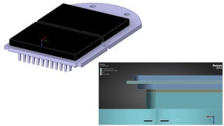
A complete PFC+AHB 140 W, PD 3.1 evaluation board (EVB) (Figure 5) has been built and tested for functionality and performance. The design achieves an impressive 100 cc estimated cased size, with 1.4 W/cc power density. The EVB includes optimized PFC, AHB, and SR power stages and magnetics and uses off-the-shelf controllers. The PFC and AHB power trains are designed around the NV6138A GaNSense power IC and the NV6245C GaNSense half-bridge IC. The EVB also includes EMI filtering and passes both conducted and radiated emissions.

Figure 5. 140 W, PD 3.1 evaluation board, efficiency = 94.5%, estimated cased size = 100 cc. Image used courtesy of Bodo’s Power Systems [PDF]
The full-load boost PFC waveforms are shown in Figure 6. During 115 VAC line input, the boost circuit operates in zero-voltage switching (ZVS) conditions, where the boost-switched node-voltage (VSW) slews down to zero before the GaN power FET turns on in each switching cycle. During 230 VAC line input, the boost circuit operates in partial-ZVS conditions, where VSW slews down to approximately 100 V and then hard-switches from there to zero. The controller automatically detects the valley of the VSW node during the off-time for turning on again each switching cycle to optimize the turn-on point at the lowest voltage level possible to minimize hard-switching losses. Since GaN power ICs have very-low output capacitance, the drain voltage will slew quickly down to the valley each cycle. The controller must have fast valley detection to ensure that turn-on occurs at the lowest point before the VSW voltage can ring back up. The boost-follower function can also be seen working with the DC bus voltage down at 300 VDC during low-line conditions and up at 400 VDC during high-line conditions.

Figure 6. Boost PFC switching waveforms during full load conditions, 115 VAC input (left), 230 VAC input (right), IL=blue (1 A/div), VDS=yellow (100 V/div). Image used courtesy of Bodo’s Power Systems [PDF]
The AHB half-bridge switch node (VSW) and tank current (IL) waveforms during 115 VAC input and full load conditions are shown in Figure 7. The resonant tank current ramps up linearly during each half-bridge low-side on time and then resonates during each half-bridge high side on time. This results in clean and smooth ZVS operation at the GaNSense half-bridge IC VSW output node during each switching cycle. The AHB operating frequency ranges from 125 to 300 kHz, depending on the input line and output load conditions.

Figure 7. AHB switching waveforms during 115 VAC input and full load conditions, IL=blue ( 2 A/div), VSW=yellow (100 V/div). Image used courtesy of Bodo’s Power Systems [PDF]
The efficiency curves (Figure 8) show 4-point and maximum load efficiency. This design achieves amazing 94.5% full-load efficiency at 90 VAC input which is at least 1% higher than the state-of-the-art product, representing up to 20% energy savings. The efficiency at 90 VAC and full load is the efficiency that determines the cased size and resulting case touch temperature of the final adapter product.

Figure 8. 4-point efficiency (left) and maximum load efficiency (right) curves. Image used courtesy of Bodo’s Power Systems [PDF]
Finally, the conducted and radiated EMI is always a major concern with power supply designs. New designs with GaN continuously come into question concerning challenges with EMI due to the faster switching speeds and frequencies. Designers typically do not tackle the EMI portion of their design until it is nearing the completion phase, only to be surprised and learn that the emissions are far above the allowable limits. The EMI scans for this design (Figure 9) show that both conducted and radiated EMI are well below the limits with sufficient margin for manufacturing tolerances. These results are achievable by implementing proper EMI guidelines as early in the design phase as possible and include such good practices as PCB ground planes, inductor shielding, properly designed EMI filter components, correct PCB floor planning, and component locations and proximity.

Figure 9. Conducted emissions at 115 VAC/140 W (left) and radiated emissions at 230 VAC/140 W (right). Image used courtesy of Bodo’s Power Systems [PDF]
High-Density Design Summary
With the industry pursuing higher-density designs, GaNSense power ICs and GaNSense half-bridge ICs lead to higher frequencies, improving existing topologies, unlocking future topologies, and ultimately achieving higher efficiencies. Next-generation, high-frequency controllers are also required, as well as new magnetic materials to enable a complete high-speed eco-system, enabling lower temperatures and smaller sizes. Improving existing PFC circuits or using new circuits such as AHB are only small examples of what is possible. More innovation is waiting around the corner as GaN continues to improve and unlock existing and new topologies.
References (www.navitassemi.com)
1.) GaNFast NV6123, NV6125, NV6127 datasheets, Navitas Semiconductor, 2019
2.) GaNFast NV613x power ICs with GaNSense technology datasheets, Navitas Semiconductor, 2022
3.) GaNSense NV624x half-bridge ICs datasheets, Navitas Semiconductor, 2022
4.) Xiucheng Huang, An Ultra-High Efficiency High Power Density 140W PD3.1 AC-DC Adapter Using GaN Power ICs, APEC Technical Paper, 2023
This article originally appeared in Bodo’s Power Systems [PDF] magazine
Featured image used courtesy of Adobe Stock