Facebook
 Google
 GitHub
 Linkedin
Enabling High Efficiency: Gate Driver ICs for Automotive Traction Inverters
E-mobility is driving significant demand for power electronics, particularly inverters. High-performance power modules help ensure efficient designs.
This article is published by EEPower as part of an exclusive digital content partnership with Bodo’s Power Systems.
Article co-authored by Bosch's Christopher Wille, Thoralf Rosahl, and Andreas Menzel.
To improve overall performance, many are replacing traditional SiIGBTs with SiC-MOSFETs and adopting more advanced packaging technologies and innovative design processes.

Image used courtesy of Bodo’s Power Systems [PDF]
However, this represents only one of the numerous optimization strategies. A different path focuses on the control of switching behavior. By upgrading to advanced gate driver ICs, manufacturers can influence and optimize the switching performance, losses, and robustness without the need for a complete redesign of the set-up and architecture. This minimally invasive alternative raises a key question: How do different gate-driving topologies influence system efficiency, and what improvements can be achieved simply by changing the way power devices are driven?
Beyond VSGD: Exploring Current-Source and Gate-Shaping Approaches
Most designs today rely on voltage-source gate driver (VSGD) ICs, which regulate the turn-on and turn-off of power devices by applying high and low gate-source voltages. To better understand how alternative driving concepts influence overall system performance, Bosch initiated a research into different gate-driver topologies, focusing on current-source gate drivers (CSGDs) and adaptive gateshaping gate drivers (GSGDs).
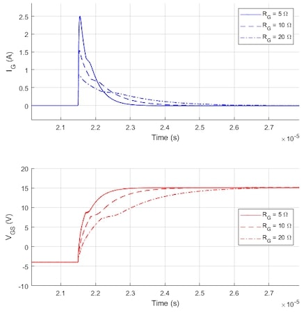
a) Voltage source gate driver
b) Current source gate driver
Figure 1. Typical gate voltage and current waveforms of voltage source gate driver (a.) and current source gate driver (b.) with different gate resistances. Image used courtesy of Bodo’s Power Systems [PDF]
CSGDs drive the power transistor with a controlled gate current (IG), enabling precise management of the gate charge (QG) and fine-tuning of dv/dt and di/dt. The imposed IG still causes a voltage drop across the gate resistance (RGint) inside the power transistor or power module. However, there is no RGext between the driver output and the power transistor anymore, which typically defines the switching behavior in VSGD implementations.
Figures 1(a) and 1(b) illustrate typical VGS and IG waveforms for VSGD and CSGD under different external RG values. Notably, the gate current remains constant in CSGD operation. In a VSGD, the peak IG scales approximately with 1/RG, and the Miller plateau makes dv/dt highly dependent on RG, forcing a tradeoff between switching losses and electromagnetic interference (EMI). In addition to these effects, another critical parameter is the voltage overshoot generated during switching, caused by parasitic inductances in the circuit layout.
In contrast, a CSGD regulates IG directly, producing an almost RGindependent VGS ramp and predictable dv/dt through the Miller plateau. This reduces overshoot, ringing, and switching losses. In practice, a small RG is retained for damping and segmented gatecurrent profiles can be programmed to balance switching speed and EMC requirements, improving repeatability, efficiency, and overall system reliability.
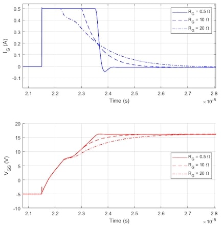
Unlike conventional VSGDs or CSGDs, the GSGD considered here can continuously vary the gate current (IG) throughout the switching transition. This technique is specifically known as gate-current shaping (GS). The resulting gate-current profile is a time-ordered sequence of IG setpoints, where each segment is defined by a programmed current amplitude and its corresponding time interval. The Bosch gate driver makes it possible to select the optimum waveform for the system.
Figures 2(a) and 2(b) illustrate the power device’s switching waveforms under a GSGD that continuously shapes IG during turn-on and turn-off, respectively. During a turn-on event, staged current segments (IGon1–IGon4) pre-charge the gate, control di/dt and dv/ dt through the Miller plateau, and balance a fast VDS falling slope against reduced reverse-recovery and switching losses. During a turn-off event, a pre-discharge followed by controlled discharge segments (IGoff1–IGoff4) shapes dv/dt and di/dt across the Miller plateau to minimize VDS overshoot and EMI while shortening the transition.
a) Turn on
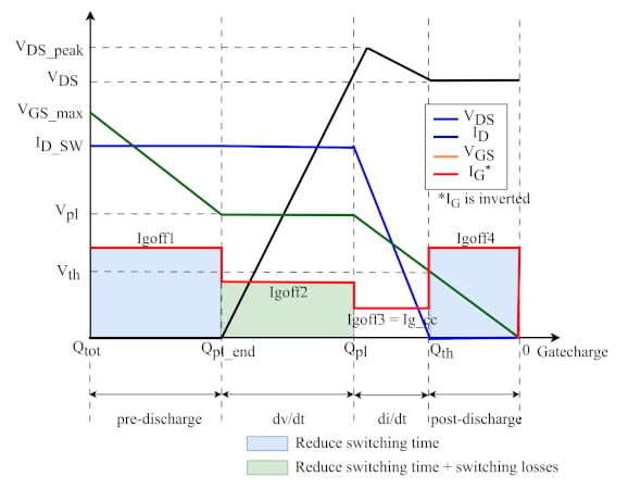
b) Turn off
Figure 2. Current control gate driver turn-on (a.) and turn-off (b.) modelling with gate shaping. Image used courtesy of Bodo’s Power Systems [PDF]
Advancing Switching Performance with the EG120’s Programmable Gate-Current Profiles
Bosch’s EG120, a CSGD IC featuring programmable gate-current shaping, served as the GSGD in this study and underpins the reported double-pulse and inverter-level comparisons. Different IG profiles are applied in the turn-on and turn-off phases. The device supports up to six segments for turn-on and five for turn-off, with up to 133 profiles that can be stored in the on-chip memory and selected in real time based on changing operating conditions such as DC-link voltage (VDC), switching current (ISW), and temperature (T), allowing the driver to optimize overshoot, EMI, and switching losses.
To evaluate the impact of the gate driver topology on overall system performance, a benchmarking experiment was conducted using two identical architectures. One system incorporated VSGD ICs, while the other utilized the GSGD EG120 ICs. All other conditions, including the power modules, the DC-link capacitor and the cooling system, were strictly kept the same to ensure that the driver-chip type was the sole independent variable for accurate performance assessment.
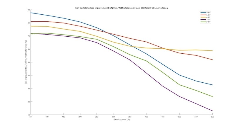
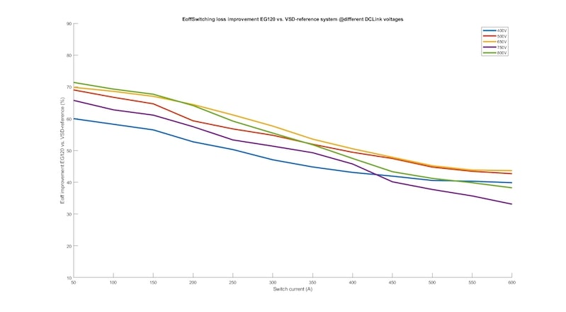
Compared to a VSGD baseline, the turn-on event shows up to a 90% reduction in turn-on energy at bus voltages from 400 V to 800 V. During the turn-off event, the EG120 likewise achieves coordinated loss reduction: optimized IG shaping combined with an active Miller clamp suppresses overshoot and ringing, thereby lowering thermal stress and enhancing device reliability. The results for switching efficiency improvements and IG profiles across different VDC levels during turn-on and turn-off events are presented in Figure 3.
a) Turn on
b) Turn off
Figure 3. EG120 double pulse test – turn-on efficiency curve (a.) and turn-off efficiency curve (b.). Image used courtesy of Bodo’s Power Systems [PDF]
System-Level Testing on Motor Bench
Across the full operating load, VDS overshoot was limited to a maximum of VDC_link +300 V. The power module used in the doublepulse tests is rated 1200 V. Based on these results, the selected IG shaping profile was deployed and evaluated on a motor test bench to assess its impact on switching losses and drive efficiency.
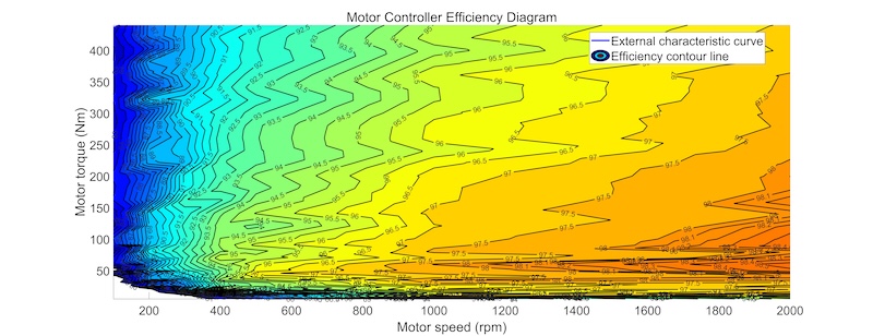
The motor test bench was configured with a 650 V DC bus supply and a 380 V AC-rated motor, operating at a 10 kHz carrier frequency and an ambient temperature of 25 °C. At a rated torque of 230 Nm and a speed of 6855 rpm, the system delivered 165 kW of mechanical output power. Figure 4 illustrates the inverter efficiency map comparing VSGD and EG120 gate drivers. The X-axis represents motor speed (0-10,000 rpm), while the Y-axis represents motor torque (0-400 Nm). Efficiency isolines highlight performance differences across the operation range.
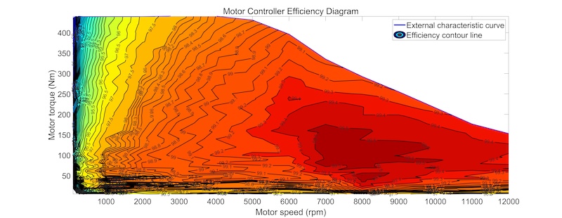
a) Conventional voltage-source gate driver
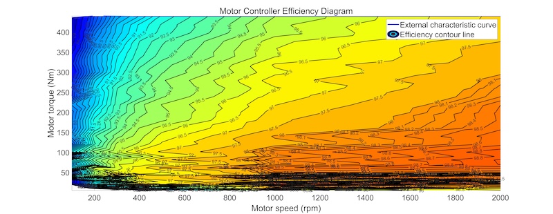
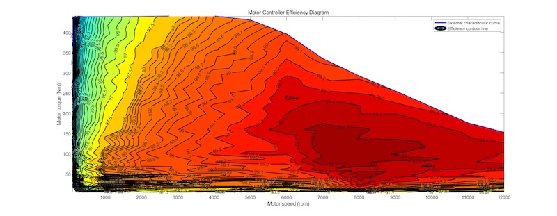
b) Bosch EG120 gate driver
Figure 4. Torque-speed characteristics comparing conventional voltage-source gate driver (a.) with a Bosch EG120 (b.) at different operating conditions. Image used courtesy of Bodo’s Power Systems [PDF]
Under identical test conditions, the EG120-based inverter achieved a peak conversion efficiency of 99.6% and maintained ≥99.4% at the rated operation conditions (230 Nm, 6,855 rpm, 165 kW). At partial loads of 25% (57.5 Nm), 50% (115 Nm) and 75% (172.5 Nm), the measured efficiencies were 99.49%, 99.57%, and 99.49%, indicating stable high efficiency across the operating range. The VSGD baseline measured 99.43%, 99.40%, and 99.34% at the corresponding load points, i.e., gains of approximately 0.06-0.17 percentage points with EG120.
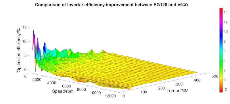
Figure 5. 3D efficiency and loss map for EG120 vs. baseline. Image used courtesy of Bodo’s Power Systems [PDF]
Efficiency analysis shows that using a gate-shaping SiC-MOSFET driver shifts the whole efficiency map upwards to higher efficiency values, the high-efficiency “red zone” expands, and new efficiency peaks emerge. For urban speeds of 20-30 km/h, the motor typically operates at 1300-2400 rpm, where efficiency improvements range from 0.2 to 0.6 percentage points.
Compared to the VSGD baseline, the EG120 sustains high efficiency across a broader operating envelope, with more uniform distribution and fewer low-efficiency regions. The 3D plot (Figure 5) confirms lower system losses, and a reduced peak-to-valley spread.
Conclusion
The results show that meaningful efficiency gains in emobility inverters do not require a redesign of the power stage. By upgrading only the gate driver, Bosch’s EG120 delivers lower switching losses, reduced overshoot, and a consistently higher efficiency map across the full operating range. These improvements translate directly from double-pulse measurements to real motor bench performance, with gains of up to 0.6 percentage points in typical driving conditions.
In a nutshell, programmable gate-current shaping offers a practical, minimally invasive way to enhance inverter efficiency while keeping existing hardware architectures mostly unchanged. Future work will focus on extending these results through adaptive, AIdriven optimization strategies that dynamically adjust gate-current profiles across an even wider range of operating conditions.
This article originally appeared in Bodo’s Power Systems [PDF] magazine and is co-authored by Lan Fang (Corresponding author), Christopher Wille, Thoralf Rosahl, Andreas Menzel, all Robert Bosch GmbH.