 Facebook
 Google
 GitHub
 Linkedin
Operating Principles of Single-Phase AC Voltage Controllers
This article explores the operating principles of a single-phase AC voltage controller, including protection circuitry and calculations, as well as the application and significance of voltage controllers in modern electrical systems.
A thyristor controller, otherwise known as a single-phase AC voltage controller, is an electric component utilized in the adjustment of the supply voltage of a load. The voltage controller is also known as the phase angle controller. This controller controls the conduction angle of the thyristor and is widely used in motor control, heating, power regulations, and lighting.
Operating Principle of Single-phase AC Controllers
The operating principle of a single-phase AC controller is based on the control of the angular conduction of the thyristor, which is a single-controlled rectifier (SCR) switch that permits the flow of current in only one direction. In a switching circuit, the thyristor can be arranged in parallel to make the flow of current through the load possible in either direction.
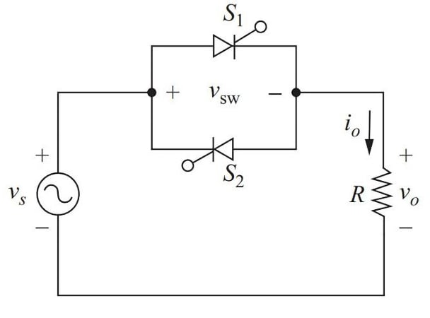
Figure 1. Parallel thyristor connection in the electronic switching. Image used courtesy of Bob Odhiambo
The thyristor turns on when a positive voltage is applied, allowing the flow of current through the gate’s terminals. The thyristor stays on even after removing the input voltage until a certain current threshold is reached.
The single-phase AC voltage controller works in a similar operating principle to a half-wave rectifier circuit. In the first positive half-wave signal of the voltage source Vs, S1 conducts until the zero point is reached. During the negative half cycle of Vs, S2 switches on having a period later than S1. This switching of S1 allows for the flow of a negative load current.
In Figure 1, both S1 and S2 cannot be on at the same time; therefore, the source voltage Vs flowing through either switch is the same as the one flowing through the load. Due to the unidirectional nature of the SCR, the average current flowing through is not zero. The phase angle at which the thyristor is triggered is the conduction angle. By adjusting the pulse gate's time, the thyristor's conduction angle can be controlled.
Voltage Across the Resistive Load
The waveforms of voltage for a single-phase AC voltage controller with a resistive load in phase angle control are shown in Figure 2. The AC voltage waveform can be seen in an incandescent light dimmer circuit. The waveform of the AC voltage source is represented by Vs, while the voltage across the switch is Vsw. The firing angle of the thyristor is given by .
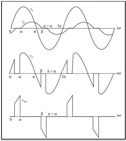
Figure 2. Waveforms of voltage for a single-phase AC voltage controller with a resistive load. Image used courtesy of Bob Odhiambo
To determine the output voltage Vo that flows through the resistive load (RL), a couple of calculations need to be considered. The voltage in the RL can be expressed as follows:
\[V_{o(\omega t)}=Vm\,sin\,\omega t\]
Where the equation is an evaluation of the sinusoidal AC voltage waveform in which there is a variation of voltage to time. In the equation, Vm is the peak amplitude of the instantaneous voltage Vs and ωt is the time, where is the angular frequency of the wave in radians per second, and t represents time in seconds.
Root Mean Square Load Voltage
The evaluation of the waveform’s half period can be done by determining the root mean square (RMS) of the load voltage. We can therefore express the RMS load voltage as follows:
\[V_{o(rms)}=\sqrt{\frac{1}{\pi}\int\limits^{\pi}_{a}[Vm\,Sin(\omega t)]^{2}d(\omega t)}=\frac{V_{S}}{\sqrt{2}}\times\sqrt{\frac{(1-cos\,cos(a))}{2}}\]
Where Vs is the voltage source and is the firing angle of the thyristor.
Example Calculation
An AC voltage waveform has a peak voltage of 100 V, a firing degree of 60 degrees, and an average voltage of 50 V. Calculate the RMS voltage across the load.
\[V_{o(rms)}=\frac{V_{S}}{\sqrt{2}}\times\sqrt{\frac{(1-cos\,cos(a))}{2}}\]
Substitute the peak voltage of the voltage source Vs in the formula
\[V_{o(rms)}=\frac{100V}{\sqrt{2}}\times\sqrt{\frac{(1-cos\,cos(60))}{2}}\]
\[\frac{(1-cos\,cos\,(60))}{2}=0.25\]
\[V_{o(rms)}=\frac{100V}{\sqrt{2}}\times\sqrt{0.25}\]
\[V_{o(rms)}=70.7\times0.5\]
\[V_{o(rms)}=35.4V\]
The RMS across the load is therefore approximately 35.4 V. It is important to note that there are assumptions that are taken into consideration during the RMS calculations. The assumption is that the load current is in phase with the voltage across the load, and there is zero voltage drop across the thyristor.
Protection Circuitry in Single-Phase AC Voltage Controllers
AC voltage controller should be able to provide precise control while working in an optimal state. To make it practical, a protection circuit is used to prevent failure and faults that might damage the controller and the load.
Types of Protection Circuitry
Below are some variants of protection circuitry for an AC voltage controller.
Overvoltage protection: This method restricts voltage flow through the RL to a safer level. Without overvoltage protection, the rise of voltage above the rating of the RL may cause damage to it. This form of protection can be done using a Zener diode or a variable resistor connected in parallel with the load.
Thermal protection: This ensures the controller is shielded from excess heat. Overheating can result in excessive current flow that can damage the controller. This form of protection uses thermal switches to interrupt the current flow if the rated value is exceeded.
Snubber circuit: This circuit is used in the suppression of high-frequency voltage transients that occurs during the switching process of the thyristor controller. The circuit is made up of a resistor and a capacitor that are connected in parallel with the thyristor, where the capacitor is utilized in the suppression of the voltage transient, and the resistor is used to control the rate at which the voltage across the resistor rises.
Overcurrent protection: This type of protection limits the current flowing in the controller. Overcurrent is an issue that can result from an overload condition of the load or a short circuit. To protect the controller from overcurrent, a circuit breaker or a fuse with the controller's rating is used to interrupt the flow if the rating is exceeded.
Applications of Single-Phase AC Voltage Controllers
A single-phase voltage controller can be used to dim light systems by regulating the voltage flowing in the system. The intensity of the lamp reduces with the reduction in voltage in the system, making it suitable for use in areas such as auditoriums and theaters.
Heating applications such as ironing often require regulating their heating temperature. This is where the voltage controller comes in to adjust the voltage flowing in the heating element to control the temperature and allow for optimal and efficient operations of the heating systems.
In motors, the voltage controller can be used to control how fast the motor rotates by controlling the voltage flowing through its windings. This makes varying motor speeds easy. The controller can also be applied to various home appliances, including refrigerators and air conditioners.
Advantages of Single-Phase AC Voltage Controllers
The single-phase voltage controller is vital in allowing for flexibility in voltage control in systems that require regulation with vast application in electrical systems. In the design of these controllers, the load characteristics and rating are considered to provide an efficient and stable operation that works at its optimal state. The controller design should endure voltage fluctuations to provide an output that has consistency and smoothness.
The significance of single-phase AC voltage controllers in modern electrical systems cannot be overstated. With the increasing demand for energy efficiency and renewable energy sources, the ability to control and regulate voltage levels is becoming increasingly important. Single-phase AC voltage controllers are also an essential component in smart grid systems, which rely on advanced control technologies to manage the flow of electricity and improve the stability and reliability of the power supply.
Takeaways of AC Voltage Controllers
- A thyristor regulator, also known as a single-phase AC voltage regulator, controls the force voltage of a load and is extensively used in motor control, heating, power regulation, and lighting.
- The operating principle of a single-phase AC regulator is grounded on the control of the angular conduction of the thyristor.
- The RMS load voltage can be calculated using the formula;
\[V_{o(rms)}=\frac{V_{S}}{\sqrt{2}}\times\sqrt{\frac{(1-cos\,cos(a))}{2}}\]
- The voltage across the resistive load in a single-phase AC controller can be evaluated using the formula:
\[V_{o(\omega t)}=Vm\,sin\,\omega t\]
- Protection circuitry for an AC voltage regulator is used to help prevent failure and faults that might damage the regulator and the load.
- Types of protection circuitry include overvoltage protection, thermal protection, and current protection.
Featured image used courtesy of Adobe Stock


Nice Article.