Facebook
 Google
 GitHub
 Linkedin
Substation Commissioning and Testing—Part 3: Field Testing
Substation field testing ensures long-term reliability. It verifies instrument transformers , circuit breakers, and protection relays against industry standards.
Commissioning sets the technical baseline for long-term reliability, confirming that equipment is installed correctly, wired as designed, and ready to perform under faults and normal load. A disciplined program ties factory data, protection studies, and field measurements into a single, traceable package before first energization.
Industry references such as the ANSI/NETA Acceptance Testing Specifications (ATS) offer structured scopes and minimum tests across major asset classes, while equipment- and function-specific standards provide the details that guide pass/fail criteria. Together they define what “ready for service” means in objective terms.
Instrument Transformer Verification
Accurate instrument transformers establish the foundation for protection and metering functions. Field tests confirm ratio and polarity, assess saturation behavior, validate burdens, and verify grounding practices and circuit segregation.
CT Ratio, Polarity, and Saturation Checks
Ratio and polarity: Confirm CT ratio by secondary injection across all taps used by protection and metering. Observe polarity markings (P1/P2, S1/S2) and validate with a quick dc-pulse or low-voltage ac check before applying automated routines. IEEE C57.13 lists the measurement and calculation of ratio and phase angle as basic conformance tests for instrument transformers.
Saturation and excitation: Establish the knee point and excitation curve to verify the specified protection class. Automated sets (such as CT analyzers) determine equivalent circuit parameters, knee point, composite error, and transient classes (TPX, TPY, TPZ) while also demagnetizing the core after testing. These results can be directly evaluated against IEC/IEEE criteria.
Note: Multi-ratio CTs should be tested on every utilized tap; modern analyzers can measure multiple taps in a single run and calculate errors and knee points per standard methods.
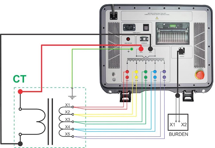
Figure 1. Muti-tap CT turns ratio. Image used courtesy of DV Power.
VT/PT Ratio and Burden Verification
For inductive VTs, confirm the ratio, phase displacement, and burden within the class limits. IEC 61869‑3 defines accuracy classes for measuring and protective VTs (for example, 0.1, 0.2, 0.5, 1.0 for measuring; 3P and 6P for protective) with limits over specified burden ranges and 80–120% of rated voltage. Field checks should include measuring connected burden in VA and power factor to ensure the secondary circuit remains within rated burden.
Documenting actual connected burden and confirming it against the transformer’s thermal and accuracy ratings prevents unintended metering or protection error.
Secondary Grounding Confirmation
Instrument transformer secondaries should be grounded at a single point to control induced and fault-condition voltages on secondary circuits. The updated IEEE Guide C57.13.3 addresses grounding practices for CT and VT secondary circuits. Verification during commissioning includes tracing the grounding conductor, confirming the bond location, and ensuring no inadvertent multiple grounds exist.
Protection vs. Metering Circuit Validation
Protection and revenue metering typically require separate cores and, in many utilities, physically segregated circuits. Confirm that:
CT/VT ratios in the relay/MU settings match the installed transformer nameplates.
Protection cores meet the required accuracy at fault currents (protection classes) while metering cores achieve revenue accuracy at normal loads (metering classes). IEEE C57.13 and IEC 61869 establish these class definitions and test codes.
During wiring checks, validate that dedicated core leads terminate only on intended devices, test switches are appropriately configured, and burdens remain within the transformer rating when all connected devices are accounted for. Automated CT/VT analyzers can also measure burden at the terminals to confirm compliance.
Circuit Breaker Commissioning Tests
Acceptance testing demonstrates that the breaker operates to its nameplate performance and interworks correctly with auxiliary circuits, interlocks, and protection commands.
Mechanical Operation and Timing Tests (Open/Close/Trip)
Perform timed sequences—O (open), C (close), CO (close–open), O‑CO, and O‑CO‑CO—to verify opening and closing times, pole spread, and sequence behavior. IEC 62271‑100 defines operating sequences and rated operating sequence notation (O – t – CO – t′ – CO) and has been updated via Amendment 1:2024; align test plans and acceptance documentation with the updated definitions. Test systems provide automatic timing, capture auxiliary contacts, and calculate time intervals per sequence.
Trip‑Coil and Close‑Coil Current Profiling
Coil current signatures reveal latch friction, undervoltage conditions, or auxiliary contact issues. A healthy signature typically shows an initial current rise, a dip and inflection when the armature moves, a final rise to steady state, and a decay at contact interruption. Breaker analyzers record coil current along with station voltage to correlate slow operation with low control voltage or mechanical drag. Use these signatures to set minimum pickup and pulse duration checks.
Contact Travel and Velocity
For mechanisms that support transducers, record contact motion, stroke, and velocity. Deviations from manufacturer reference data often indicate mechanism wear or lubrication issues. Many timing systems include displacement inputs and compute velocity between user-defined points, producing a consolidated report with timing and travel.
SF₆ Density and Vacuum Interrupter Checks
Gas-insulated equipment: Modern GIS requires temperature-compensated density monitoring rather than pressure alone. IEC 62271‑203 mandates continuous monitoring in each gas compartment with alarm thresholds for functional density; IEC 62271‑1 further addresses gas quality, moisture limits, and the use of SF₆ that conforms to IEC 60376 or reclaimed gas per IEC 60480. Commissioning includes sensor functional checks, dew point measurement, and verification of alarm/trip wiring back to the station control system.
Vacuum interrupters: Integrity is typically verified per manufacturer instructions—often via a vacuum bottle test using a dedicated high‑potential source with contacts open. While method details are manufacturer‑specific, the foundational breaker standard IEC 62271‑100 applies to AC circuit‑breakers and provides the framework for dielectric capabilities and routine checks.
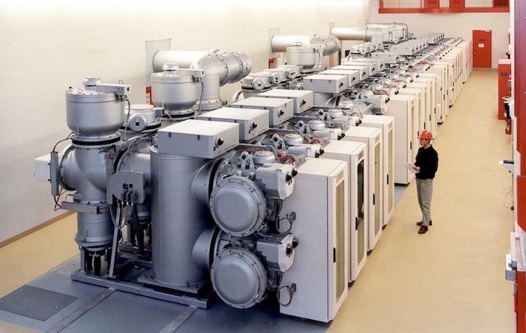
Figure 2. Gas insulated switchgear. Image used courtesy of Wikimedia.
Interlocking and Anti‑Pump Verification
Functional safety requires that mechanical and electrical interlocks work as intended: racked positions interlocked with shutters, doors with earthing switches, and permissives that prevent incorrect sequences. IEC 62271‑200 details interlocks and access rules for metal‑enclosed switchgear up to 52 kV, with Amendment 1 (2024) clarifying door/access and interlock forces during testing.
Anti‑pump features ensure that a maintained close command does not cause repetitive close–trip cycling; vendor application notes (such as Schneider Electric, GE, Siemens) explain expected behavior and test steps to confirm it.
Protection Relay Testing
Protection system commissioning progresses from configuration checks to element testing and finally scheme and end‑to‑end validation. Maintain traceable records linking the coordination study, device settings, and test results.
Configuration and Settings Verification
Settings vs. coordination study: Before any energization or injection, confirm that relay settings match the latest coordination study. Use device function numbers to keep reports unambiguous: such as 50/51 (instantaneous/time overcurrent), 67 (directional overcurrent), 87 (differential), 21 (distance). The latest IEEE C37.2 standard defines function numbers and acronyms used throughout drawings and relay settings, enabling consistent interpretation during walk‑downs and test sheet creation.
CT/VT ratios, logic schemes, protection groups: Map ratios and wiring polarity to settings; confirm group switching, reclosing coordination, breaker failure inputs (50BF/62), and interlocking inputs. Acceptance often uses a structured checklist cross‑referencing the protection one‑line, logic diagrams, and trip matrices.
Time synchronization: Modern schemes require sub‑microsecond alignment for sampled values and GOOSE time tagging in digital substations. IRIG‑B is prevalent for legacy serial distribution, while the IEC/IEEE 61850‑9‑3 power profile (PTP) provides Ethernet‑based time with ±1 μs end‑device targets and a defined accuracy budget across boundary/transparent clocks. Verification includes checking grandmaster status, PTP state, offset from master, and failover behavior.
Secondary Injection Testing
Element‑by‑element: Using a calibrated test set, inject currents and voltages to verify each enabled protection element:
- Overcurrent (50/51): Confirm phase and ground pickups and inverse‑time curves against the coordination study. Directional elements (67) require appropriate polarizing voltage/current conditions.
- Differential (87): Check pickup, restraint behavior, and harmonic blocking or inrush logic where used.
- Distance (21): Validate zone reaches and characteristics with appropriate source impedance ratios. Device numbers and function definitions per IEEE C37.2 help align test records with settings and as‑found logic.
Pickup, timing, and dropout: For each element, record pickup values, timing at two or more test points, and dropout to ensure margins against load and CT/VT errors. Confirm that timers, seal‑in elements, and trip outputs operate the intended lockout and breaker coils.
Logic and interlock validation: Scheme logic—including 86 lockout behavior, breaker failure initiation/supervision, reclose blocks, and permissive/trip outputs—is validated with simulated statuses (breaker aux switches, gas/pressure alarms, interlocks). This functional testing bridges the gap from pure measurement to actual switching device operation defined in the design logic.
End‑to‑End and Scheme Testing
Line protection and differential schemes: End‑to‑end testing applies synchronized sources at each terminal to emulate real faults and load conditions, proving directional decisions, current reversal handling, weak‑infeed logic, and differential restraint. Test tools synchronize via GPS/IRIG‑B or PTP to align waveforms and event capture. System‑based testing platforms provide predefined cases for line differential and distance protection, including charging current and external fault scenarios that must not trip.
Channel verification (fiber, PLC, microwave): Before scheme logic tests, verify the teleprotection path for latency, Bit Error Rate (BER), and alarm behavior. IEEE C37.94 defines a widely used optical interface between teleprotection and multiplexers (N×64 kbps), while IEC 60834‑1 specifies performance and testing for narrow‑band command teleprotection, covering PLC and leased or radio links. Channel health and alarm integration into relay logic are essential acceptance points.
Permissive, Blocking, and Transfer‑Trip Logic
Permissive overreaching transfer trip (POTT): Local overreaching elements key a permissive signal; tripping requires both local detection and receipt of permission from the remote end. WEI (“weak‑end infeed”) logic and echo features address low‑infeed scenarios.
Blocking (DCB): A reverse‑looking element keys a blocking signal for external faults; tripping occurs when the local forward element operates without receiving a block. Channel speed and dependability are critical.
Direct/transfer trip (DTT/PUTT/DUTT): A trip command is sent to the remote end without the remote relay’s independent decision, so channel security is critical; commissioning verifies permissive paths, direct trip paths, and interlocks that supervise transfer trip reception.
Scheme testing exercises these logics across multiple fault locations and source conditions, confirming acceleration, security under external faults, current‑reversal handling on parallel circuits, and correct interaction with reclosing and breaker failure. Combined with documented instrument‑transformer checks and breaker timing, end‑to‑end tests complete the functional validation of protection systems.
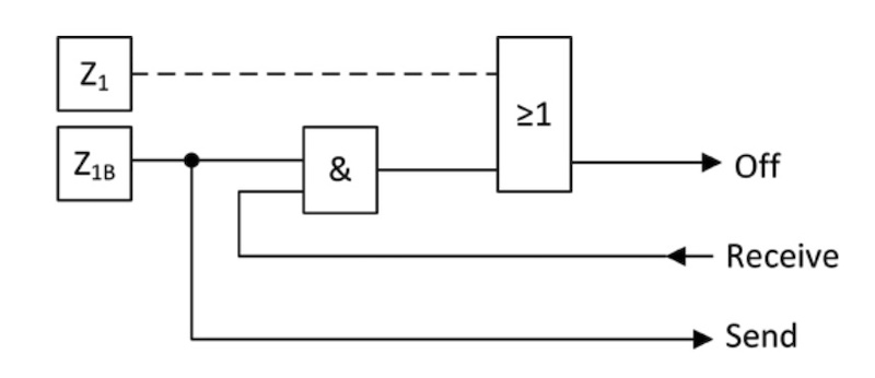
Figure 3. Distance Protection with Permissive Overreaching Transfer Trip (POTT). Image used courtesy of EE Online.
Comprehensive Set of Measurements and Checks
A successful substation commissioning program integrates precise measurements, functional demonstrations, and standards‑based acceptance criteria. Instrument transformers are verified for ratio, polarity, excitation behavior, burden, and single‑point grounding so that relays and meters receive accurate signals.
Circuit breakers are proven mechanically and electrically—with timing, motion, coil profiling, gas or vacuum checks, and interlocking/anti‑pump validation—before any scheme logic is exercised. Protection relays are confirmed against the coordination study, then validated function‑by‑function through secondary injection and ultimately proven as a system through end‑to‑end tests with synchronized time.
Adhering to recognized references—from NETA ATS to IEEE C37 series, IEC 61869, and IEC/IEEE 61850-9-3—establishes a verifiable path to energization and a high level of confidence when the first fault occurs.