Facebook
 Google
 GitHub
 Linkedin
Control Transformers: Operation, Selection, and Sizing Considerations
This article provides an overview of control transformers, emphasizing their role in converting high voltages to safer levels for controlling electrical equipment, and highlights considerations like dual-voltage connections, inrush current, sealed current, and the four steps to choosing the right control transformer.
Control transformers are crucial in converting higher voltages to lower, safer ones, enabling the control of various devices like contactors and motor starters. Dual-voltage connections in control transformers, often ranging from 240 to 480 volts for industrial use, provide flexibility. Inrush current, a temporary surge in current during startup, is a critical consideration. Control transformers must handle this high inrush current without compromising the secondary voltage, ensuring proper device operation. Sealed current, indicating the transformer's rated capacity during regular operation, is also significant. Choosing the right control transformer involves evaluating both inrush and sealed current requirements and matching them with the transformer's specifications.
Control transformers are used to transform higher voltages into lower, safer voltages for control of electrical equipment. As an illustration, a 480-volt motor can be turned on and off by a push button connected to a 24-volt supply, which is the secondary voltage of a control transformer with a primary voltage of 480 volts. The danger imposed by the 24-volt circuit is much less than that of a 480-volt circuit. Control transformers supply the power to operate contactors, motor starters, indicating lights, solenoid valves, and other devices used to control electrical equipment.
Dual-Voltage Connections
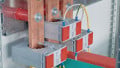
The power requirements of the control devices are usually quite small. As a result, control transformers have small KVA ratings—rarely as large as 1 KVA. Figure 1 shows a typical control transformer. In most control transformers, the H winding is dual voltage—usually 240 x 480 for industrial applications and 120 x 240 for residential uses. The X winding is usually 120 volts for industrial and 24 volts for residential applications.
![]()
Figure 1. A control transformer with dual-voltage H windings and X windings. Image used courtesy of Hubbell
The arrangement of the X winding connections allows for changing voltages by the simple connection of a jumper between terminals. The connection for the lower voltage involves connecting a jumper between the X1 and X3 terminals and another between the X2 and X4 terminals. This parallels the X windings for the lower of the two voltages. By using the same two jumpers and connecting both of them between the X2 and X3 terminals, the windings are put in series for the higher voltage.
Inrush Current
Ohm's Law requires that the voltage drop across the resistance must increase as the current through a resistance increases. As a result of this voltage drop across the resistance of the secondary transformer winding, the secondary voltage will be less with more load. Remember that an inductor has a low resistance; most of its opposition to current results from the CEMF induced in the coil. This CEMF takes a short time to develop, and until the CEMF is strong enough to oppose the applied voltage, there will be almost no opposition to current flow. In the case of a control transformer supplying an inductive load, this inrush current may be ten times higher than the device's normal operating or sealed current. Because the control transformer capacity is small and most of the devices they supply—for example, motor starter coils, relay coils, and solenoid valves—are inductive, special designs are required so the transformer can provide the high inrush current required by such inductive loads. The control transformer must be able to supply this high inrush current without allowing the secondary voltage to drop below 85% of its rated value, or there may not be sufficient voltage to operate the device.
Sealed Current
Control transformers are rated in VA for sealed current. For example, a 250 VA 240 – 120 control transformer can supply the normal or sealed VA of 250 VA, which equals 2.08 amps at 120 volts, but may also supply 18 amps of inrush current for short periods without excessive voltage drop. It is important to understand that this inrush current will only last for a very short time—perhaps 30 to 50 milliseconds. The amount of inrush current supplied determines the voltage drop across the secondary winding and, thus, the output voltage. For example, the transformer may supply 200 VA while keeping the secondary voltage at 90% of its nominal value and 260 VA with the secondary voltage at 85%. If the transformer can supply the required sealed current but the inrush current rating is too small, the secondary voltage drop may be too large, and there may not be sufficient voltage to operate the load.
Four Steps to Choosing the Right Control Transformer
To choose the proper size control transformer, both types of current—inrush and sealed—must be considered. Insufficient inrush capacity will result in a voltage that may be too low; a sealed or operating current rating that is too low will result in transformer overheating and premature failure. Use the following four steps to determine the proper size control transformer for the load:
1. From the manufacturer's data sheets, find the inrush VA rating of all the devices that will be turned on simultaneously. Then, add them to calculate the maximum inrush VA required. This means all inductive loads, indicating lamps, and other noninductive loads.
2. Determine the operating VA of all devices already on when the maximum amount of inrush VA will be required. The sum of this normal operating VA and the inrush VA of all the loads being turned on together is the total inrush current.
3. Using the control transformer specification sheets, find the control transformer with an inrush VA capacity sufficient to supply the total inrush VA calculated in Step 2. Most transformers are listed with a 90% secondary voltage inrush VA rating, meaning that the transformer can supply the listed value of inrush VA and keep the secondary voltage at at least 90% of nominal.
4. Calculate the largest operating VA of all the devices that will be on simultaneously, and then make sure that the value is less than the sealed or operating VA rating of the transformer you chose in Step 3. In most cases, the transformer will have sufficient capacity, but if there are many devices, such as indicating lights and other control devices, that stay on all the time, the sealed VA rating may not be high enough even though the inrush VA is. The transformer chosen must be able to supply the maximum operating VA and, as a result, may have a much higher inrush VA rating than is required.
Consider this example: A size two motor starter has an inrush VA of 240 and an operating VA of 29. When the starter is turned on, an indicating light that draws 20 VA is also on. What size control transformer is required? The inrush VA required is the sum of the motor starter inrush of 240 VA and the 20 VA of the indicating light for 260 VA.
The operating VA is the sum of the motor starter operating VA of 29 and the 20 VA of the indicating light, which is 49 VA. A 50 VA control transformer has a sealed VA rating of 50 and an inrush VA of 179, while a 75 VA transformer has a sealed VA of 75 and an inrush VA rating of 283. The correct choice would be the 75 VA transformer because it can supply both the required inrush and the operating VA required.
Understanding Control Transformers
Control transformers play a critical role in power systems, facilitating the safe transformation of higher voltages into lower ones for controlling electrical equipment. Understanding how that happens is essential for ensuring the proper operation and protection of various devices, such as contactors, motor starters, and solenoid valves, contributing to power systems' overall efficiency and reliability.