Facebook
 Google
 GitHub
 Linkedin
Arc Flash and Overvoltage Protection
In addition to the risk of electrical shock, other hazards are present when work is performed on or near energized electrical equipment or conductors. Two serious hazards are electrical arc flashes and electrical arc blasts.
An arc flash is a short circuit across the air. An arc blast is an explosion that happens when the surrounding air gets ionized and conductive. When insulation or isolation can no longer withstand the applied voltage, an arc flash occurs. An arc flash may occur from phase to ground or from phase to phase. The temperature of the arc flash may reach thousands of degrees and cause an arc blast. The explosion from the arc blast can spread hot gases and melting metal, damage hearing and vision, and send objects flying (see Figure 1).

Figure 1. Flash suits protect workers from the thermal energy of arc blasts. Image Courtesy of PKSAFETY
Note
According to the NFPA 70E, Standard for Electrical Safety in the Workplace, 2004 Edition, Annex K, the temperature of an arc flash can reach 35,000°F. Exposure to these very high temperatures both burns the skin and causes clothing to catch fire, aggravating the burn injury. Material and molten metal are expelled away from the arc at speeds exceeding 700 miles per hour, fast enough for shrapnel to completely penetrate the human body.
OSHA Part 1910.333 gives general requirements for safety-related work practices. OSHA inspectors also carry a copy of NFPA 70E and use it to enforce safety procedures related to arc flash. NFPA 70E gives specific guidelines on actions to be taken to comply with the general OSHA statements. The NEC® requires several types of equipment to be marked to warn qualified persons that a hazard exists (see Figure 2).
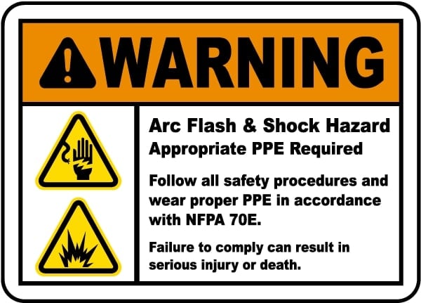
Figure 2. An arc flash warning label must be placed on any electrical equipment that may remain energized during repair or maintenance. Image Courtesy of SafetySign
The NFPA requires facility owners to perform a flash hazard analysis. A flash protection boundary must be established around electrical devices. This boundary is determined by calculations that estimate the maximum energy released and the distance that energy travels before dissipating to a safe level. Technicians working within the boundary must have appropriate personal protective equipment (PPE). The IEEE Standard 1584-2002, Guide for Performing Arc-Flash Hazard Calculations, gives procedures for determining the incident energy exposure, flash protection boundary, and level of PPE required. Incident energy is expressed in calories per centimeter squared (cal/cm2). This is a measure of the heat energy applied to a certain area of an object. The object may be a person. The flash protection boundary must be established at the point where the incident energy has fallen below 1.2 cal/cm2. It is not safe to assume that similar equipment located in different locations has the same flash protection boundary.
Overvoltage Protection
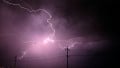
Voltage surges on a power distribution system can cause a safety hazard. A voltage surge is a higher-than-normal voltage that appears on one or more power lines for a short period of time. Voltage surges vary in voltage level and time present on power lines. One type of voltage surge is a transient voltage. A transient voltage (voltage spike) is an unwanted voltage of a very short duration in an electrical circuit. Transient voltages typically last for a very short period of time, but they are often higher in magnitude than voltage surges and are quite erratic. Transient voltages are caused by lightning strikes, unfiltered electrical components, and power being switched on and off. High transient voltages can reach thousands of volts. On a 120 V power line, a transient voltage can reach 1000 V (1 kV) or higher.
High transient voltages occur near a lightning strike or when large (very high-current) loads are shut off. For example, when a large motor (100 HP) is switched off, a transient voltage can travel down the power distribution network. An arc can be formed inside a DMM if it is connected to the system when the high transient voltage happens. Once started, the arc might induce a high-current short in the power distribution system even after the initial high transient voltage has passed. An arc blast can result from a high-current short.
The quantity of current drawn and the potential damage caused is dependent on the power distribution system's specific location. Fuse and circuit breakers are used in all power distribution systems to set current limits. As you move farther from the main distribution panel, the current rating (size) of fuses and circuit breakers reduces. The farther away from the main distribution panel, the less probable it is that the high transient voltage will cause damage.
Overvoltage Installation Categories
The IEC 1010-1 standard defines four overvoltage installation categories in which a DMM may be used (Category I — Category IV). These categories are typically abbreviated as CAT I, CAT II, CAT III, and CAT IV (see Table 1). They determine the magnitude of transient voltage a DMM or other electrical appliance needs to withstand when used on the power distribution system. For example, a DMM or other electrical appliance used in a CAT III environment must withstand a 6000 V transient voltage without causing an arc. If the DMM or other appliance is operated on voltages above 600 V, then the DMM must withstand an 8000 V transient voltage.
| Category | In Brief | Examples |
| CAT I | Electronic |
•Protected electronic equipment •Equipment connected to (source) circuits in which measures are taken to limit transient overvoltage to an appropriately low level •Any high-voltage, low-energy source derived from a high-winding-resistance transformer, such as the high-voltage section of a copier |
| CAT II | Single phase-connected loads |
•Appliances, portable tools, and other household and similar loads •Outlets and long branch circuits •Outlets at more than 30' (10m) from CAT III source •Outlets at more than 60' (20m) from CAT IV source |
| CAT III | Three-phase distribution, including single-phase lighting |
•Equipment in fixed installations, such as switchgear and polyphase motors •Bus and feeder in industrial plants •Feeders and short branch circuits and distribution panel devices •Lighting systems in larger buildings •Appliance outlets with short connections to the service entrance |
| CAT IV | Three-phase at utility connection, any outdoor conductors |
•Refers to the origin of installation, where the low-voltage connection is made to utility power •Electric meters, primary overcurrent protection equipment •Outside and service entrance, service drop from pole to building, run between meter and panel •The overhead line to the detached building |
Table 1. The IEC 1010 standard classifies the applications in which a DMM can be used into four overvoltage installation categories.
If the DMM can withstand the voltage, the DMM may be damaged, but an arc does not start, and no arc blast occurs. To protect against transient voltages, protection must be built into the test equipment. For many years, the industry followed standard IEC 348. This standard has been replaced by IEC 1010. A DMM designed to the IEC 1010 standard offers a higher level of protection. A higher CAT number specifies an electrical environment with a larger short-circuit current available, higher power available, and higher voltage transients. For instance, A DMM manufactured to the CAT III standard is more resistant to higher energy transients than a DMM manufactured to the CAT II standard.
Power distribution systems are split into categories because a dangerous transient voltage, such as a lightning strike, is attenuated when it travels through the system's impedance and system grounds. Within an IEC 1010 standard category, a higher voltage rating denotes a higher transient voltage withstanding rating. For example, a CAT III-1000 V (steady-state) rated DMM has better protection compared to a CAT III-600 V (steady-state) rated DMM. Between categories, a higher voltage rating (steady-state) might not provide higher transient voltage protection. For example, a CAT III-600 V DMM has better transient protection than a CAT II-1000 V DMM. A DMM should be chosen based on the IEC overvoltage installation category first and voltage second.