Facebook
 Google
 GitHub
 Linkedin
National Electrical Code 2023 Basics: Grounding and Bonding Part 10
Learn the grounding and bonding rules for impedance-grounded systems.
To catch up on Lorenzo Mari’s series on National Electrical Code 2023 Basics: Grounding and Bonding, please follow these links:
- National Electrical Code 2023 Basics: Grounding and Bonding Part 1
- National Electrical Code 2023 Basics: Grounding and Bonding Part 2
- National Electrical Code 2023 Basics: Grounding and Bonding Part 3
- National Electrical Code 2023 Basics: Grounding and Bonding Part 4
- National Electrical Code 2023 Basics: Grounding and Bonding Part 5
- National Electrical Code 2023 Basics: Grounding and Bonding Part 6
- National Electrical Code 2023 Basics: Grounding and Bonding Part 7
- National Electrical Code 2023 Basics: Grounding and Bonding Part 8
- National Electrical Code 2023 Basics: Grounding and Bonding Part 9
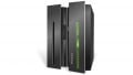
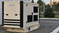
Grounding the system neutral through an impedance reduces overvoltages caused by intermittent faults. Typically, the impedance is mainly resistive and limits the magnitude of the ground-fault current. The high-resistance grounding method provides some of the advantages of ungrounded systems: continuity of service, reduced damage to equipment, and transient overvoltages of acceptable values.
Image used courtesy of I-Gard
National Electrical Code Section 250.36
Previous editions of the NEC titled Section 250.36 as “High-impedance grounded neutral systems,” covering systems between 480 V and 1 kV, and Section 250.187 as “Impedance grounded systems,” for systems above 1 kV. The current 2023 edition of the NEC changed the title of Section 250.36 to “Impedance grounded systems - 480 V to 1 kV.”
This change opens the door to a choice of methods for grounding the neutral in transformers and rotating equipment in systems between 480 V and 1 kV, such as high-resistance, low-resistance, high-reactance, and low-reactance.
Section 250.36 indicates that the impedance device is typically a resistor, and the Informational Note to Section 250.36(C) states that the impedance is selected to limit the ground-fault current to a value equal to or somewhat above the system capacitive charging current. To comply with this criterion, use a resistance value equivalent to or slightly less than the capacitive reactance to the ground.
This is the criterion of the high-resistance grounding method, suggesting that the NEC recognizes this approach as usual for the voltage range.
The high-resistance method settles two disagreeing requirements: to get enough fault current to prevent transient overvoltages while keeping its magnitude low enough to reduce damages at the ground fault location–particularly when the fault continues for a while.
At voltages greater than 1 kV, Section 250.187 indicates that the usual impedance device is a resistor. However, this section does not establish other criteria, not favoring any particular method.
High-resistance grounding is typical in industrial and commercial applications. This method introduces a resistor in a three-phase generator, power transformer, or grounding transformer neutral, limiting the line-to-ground fault current to a low value.
The method aims to maintain production with a single ground fault and suppress transient overvoltages. It appeared in the quest to find ways to reduce hazards, lessen damage to electrical infrastructure, and enhance service continuity.
There are industrial processes where continuity of service is critical–an abrupt power failure may throw the process out of control and lead to toxic chemical releases, explosions, or fires. Loss of power supply can render some machines inoperative if the product they handle solidifies inside.
The resistor also protects rotating equipment, like motors and generators, reducing iron burning damage, damping oscillations, and confining transient overvoltages to less than 2.5 times the rated line-to-neutral voltage.
Reducing the magnitude of the fault energy decreases arc-flash hazards, protecting personnel.
Section 250.36 covers impedance grounded systems from 480 V to 1 kV. This section permits the use of the method to limit current in 3-phase AC systems meeting the following conditions:
Only qualified persons maintain the installation. Only trained maintenance personnel should work on systems that can operate under a ground fault, as this is a dangerous condition. An overcurrent device will not activate after the first ground fault, so the fault current will continue until coordinating a systematic shutdown.
It is outfitted with ground detectors. These detectors alert personnel of the occurrence of a ground fault. It can be a visual or audible alarm or both.
There are no line-to-neutral loads. This rule avoids subjecting single-phase loads to voltage variations occurring under ground-fault conditions.
Section 250.36(A) Grounding Impedance Device Location
This section requires placing the grounding impedance device between the impedance grounding conductor connected to the neutral point and the grounding electrode conductor (see Figure 1).
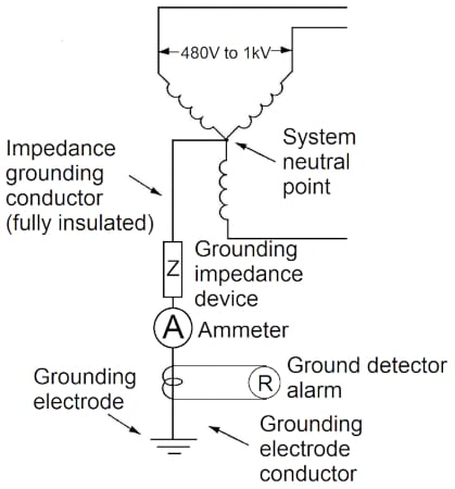
Figure 1. Location of the grounding impedance device. Image used courtesy of Lorenzo Mari
When the neutral point is unavailable, it is permitted to connect the grounding impedance device between the impedance grounding conductor connected to the neutral end of a grounding transformer and the grounding electrode conductor.
Figure 2 shows a zig-zag grounding transformer connected to a system where the neutral point is unavailable, like in delta and ungrounded-wye systems.
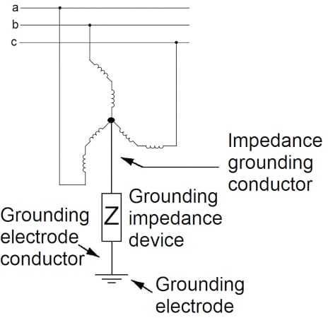
Figure 2. Grounding impedance device connected to a grounding transformer neutral. Image used courtesy of Lorenzo Mari
Section 250.36(B) Insulation and Ampacity of the Impedance Grounding Conductor
The conductor between the system neutral point and the grounding impedance device must be fully insulated to ensure that the ground-fault current will return through the impedance (see Figure 1).
The minimum ampacity of the impedance grounding conductor must be equal or more than the current rating of the impedance and not less than N° 8 AWG copper or N° 6 AWG aluminum. Mechanical considerations and not the magnitude of the fault current establish the minimum sizes of the conductors since the fault current will be low due to the limitation imposed by the impedance–usually between 1 A and 10 A.
The impedance must be rated to handle the ground-fault current magnitude continuously.
Section 250.36(C) Connection of the System Grounding
Connect the neutral point of the system to the ground only through the impedance, creating a “channel” for ground-fault current to flow through it.
Section 250.36(D) Routing of the Impedance Grounding Conductor
Since the expected ground-fault current magnitude is small, there is no concern in routing the impedance grounding conductor through a separate raceway to that of the ungrounded conductors up to the first disconnecting means or overcurrent protective device.
Connect the grounding conductor to the impedance device and not to the service cabinet. It is customary to place the impedance device in a separate enclosure close to the distribution equipment.
Section 250.24(A)(2) requires one additional grounding connection of the grounded conductor for AC services supplied from outdoor transformers. The exception to this rule permits circumventing the requirement in impedance-grounded systems because any ground current returning to the outdoor electrode will bypass the ground detector.
Section 250.36(E) Impedance Bonding Jumper
The impedance bonding jumper runs from the equipment grounding conductor terminal bar at the first disconnecting means or overcurrent protective device to the grounded side of the grounding impedance device. The impedance bonding jumper must be unspliced (see Figure 3).
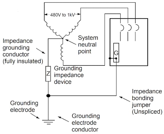
Figure 3. Unspliced impedance bonding jumper. Image used courtesy of Lorenzo Mari
Figure 4 shows the effective ground-fault current path. Note that the fault current flows through the impedance.
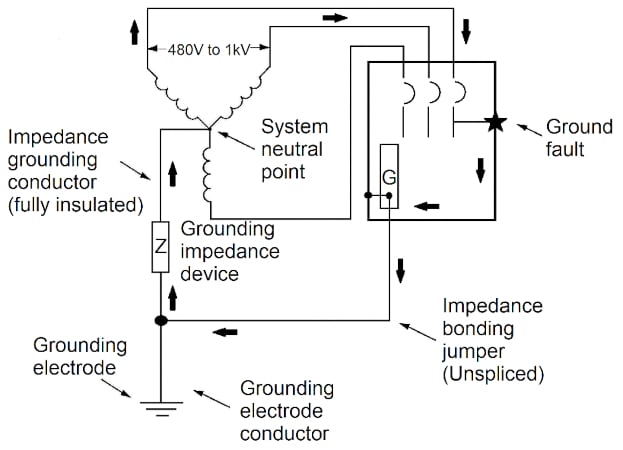
Figure 4. Effective ground-fault current path. Image used courtesy of Lorenzo Mari
Section 250.36(F) Connection of the Grounding Electrode Conductor
Connect the grounding electrode conductor anywhere from the grounded side of the grounding impedance device to the equipment grounding conductor at the first disconnecting means or overcurrent protective device. This rule covers service equipment and separately derived systems (see Figure 5).
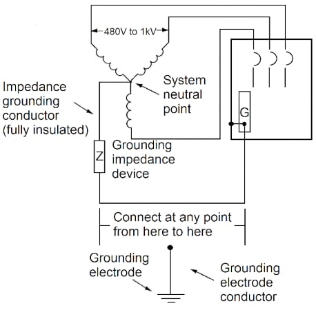
Figure 5. Location of the grounding electrode conductor connection. Image used courtesy of Lorenzo Mari
Section 250.36(G) Size of the Impedance Bonding Jumper
Size the impedance bonding jumper depending on where the grounding electrode conductor is connected.
If connected at the grounding impedance, the equipment grounding jumper is an extension of the grounding electrode conductor–size per Table 250.66 entering with the size of the largest service-entrance or derived ungrounded conductor (see Figure 6).
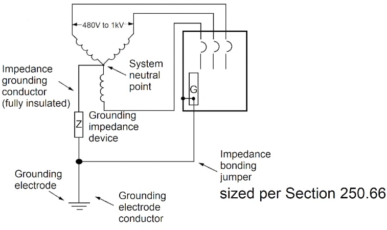
Figure 6. Grounding electrode conductor connected to the grounding impedance device. Image used courtesy of Lorenzo Mari
If connected at the first system disconnecting means or overcurrent protective device, the equipment bonding jumper is an extension of the impedance grounding conductor – size as the impedance grounding conductor per Section 250.36(B) (see Figure 7).
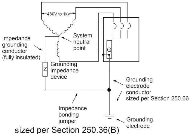
Figure 7. Grounding electrode conductor connected to the first disconnecting means. Image used courtesy of Lorenzo Mari
National Electrical Code Section 250.187
This section covers impedance grounded systems over 1 kV.
The conditions required to employ this method are the same listed in Section 250.36 for systems from 480 V to 1 kV.
Section 250.187(A) Grounding Impedance Device Location
This section requires locating the grounding impedance device between the impedance grounding conductor and the grounding electrode conductor.
Figure 8 shows a conventional high-impedance grounding scheme through a distribution single-phase transformer with the impedance introduced on the low-voltage side.
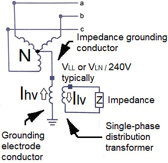
Figure 8. Grounding impedance connected through a distribution single-phase transformer. Image used courtesy of Lorenzo Mari
The impedance value on the low-voltage side is small, but the fault current sees a high value on the high-voltage side.
Section 250.187(B) Insulation of the Impedance Grounding Conductor
Insulate the impedance grounding conductor for the maximum neutral voltage.
An exception allows the impedance grounding conductor to be bare if this section and the uncovered portion of the grounding impedance device are adequately separated from the ungrounded conductors and not easily accessible.
Section 250.187(C) Connection of the System Neutral Point
Connect the system’s neutral point to the ground through the grounding impedance device only.
Section 250.187(D) Equipment Grounding Conductors
This section permits using bare conductors and requires their connection to the grounding electrode conductor and the ground bus.
Key Takeaways of Grounding and Bonding Impedance-grounded Systems
- Industrial facilities having continuous processes usually utilize resistance grounding schemes to increase service availability and reliability.
- High-impedance grounding systems improve continuity while reducing problems due to transient overvoltages.
- The NEC allows using these grounding systems if qualified maintenance personnel is available, have alarm devices, and do not feed line-to-neutral loads.
- Connect the grounding impedance device between the system neutral and the grounding electrode.
- The impedance grounding conductor must be insulated and sized not less than N° 8 AWG copper or N° 6 AWG aluminum.
- The grounding electrode conductor may be located anywhere from the grounded side of the impedance to the equipment grounding bus at the first disconnecting means or overcurrent protective device.
Featured image used courtesy of Adobe Stock