Facebook
 Google
 GitHub
 Linkedin
National Electrical Code 2023 Basics: Grounding and Bonding Part 16
Learn about the rules for bonding isolated grounding circuits and sizing bonding jumpers.
The NEC permits installing isolated grounding circuits to reduce electrical noise in electronic equipment. Properly bonding the supply side of service and the load side of overcurrent devices is vital in a suitably designed and installed grounding system.

Image used courtesy of Pixabay
National Electrical Code Section 250.96 Bonding Other Enclosures
Section 250.96(A) General Requirements
- Connect effectively all noncurrent-carrying metal parts serving as the equipment grounding conductors to ensure electrical continuity and the capacity to carry fault current safely. This requirement holds whether or not a wire-type supplementary equipment grounding conductor is present within the raceway and connected enclosures.
- Remove all non-conductive paint, enamel, or similar coating from threads, contact points, and contact surfaces, or use fittings designed to make such removal unnecessary.
The interconnected system of metal enclosures and raceways must form an effective ground-fault current path as defined in Article 100 “Definitions.” See Figure 1.

Figure 1. An interconnected system of metal enclosures and raceways. Image used courtesy of Lorenzo Mari
Section 250.96(B) Isolated Grounding Circuits
This section permits interrupting the electrical continuity of the noncurrent-carrying metal parts employed to supply power to electronic equipment susceptible to electromagnetic interference. This practice is known as “isolated equipment grounding.”
The requirements outlined in this rule are:
- Use only when needing electromagnetic interference – noise – reduction.
- Supply the equipment enclosure by one branch circuit – the conductors in the raceway supply only the individual equipment.
- Isolate from the metal raceway by one or more listed nonmetallic raceway fitting(s).
- Locate the listed nonmetallic raceway fitting(s) at the point of attachment of the metal raceway to the equipment enclosure.
- Ground the metal raceway at its supply end – granting equipment grounding for the raceway (See the Informational Note in Section 250.96(B)).
- Supplement the metal raceway with an internal insulated equipment grounding conductor. The conductor must be insulated to avert unintended contact with grounded raceways and enclosures.
Figure 2 shows an arrangement complying with the requirements above. In particular, the listed nonmetallic raceway fitting interrupts the current path between the metal conduit and the metal cabinet enclosing the electronic equipment. Also, note the insulated equipment grounding conductor connecting the service grounded bus with the enclosure’s grounding terminal assuring safety grounding – by keeping the lowest practical impedance.
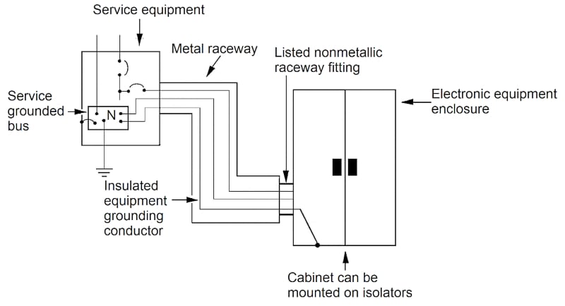
Figure 2. Electronic equipment enclosure grounded through an insulated equipment grounding conductor. Image used courtesy of Lorenzo Mari
Figure 3 shows a layout where the insulated equipment grounding conductor passes through a downstream subpanel without connection to its grounding bus. Here, the insulated equipment grounding conductor runs nonstop from the service-grounded bus to the metal enclosure’s grounding terminal.
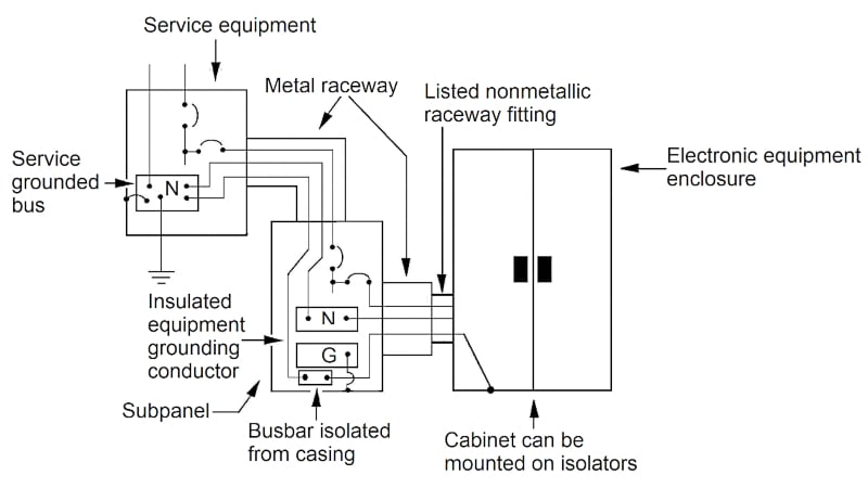
Figure 3. Insulated equipment grounding conductor passing through a sub-panel. Image used courtesy of Lorenzo Mari
Section 250.146(D) covers isolated ground receptacles for reducing electromagnetic interference in cord-and-plug-connected electronic equipment.
National Electrical Code Section 250.102 Grounded Conductor, Bonding Conductors, and Jumpers
Section 250.102(A) Materials for Bonding Jumpers
- The permitted materials for bonding jumpers are copper, aluminum, copper-clad aluminum, or other corrosion-resistant materials.
- Bonding jumpers may be wires, buses, screws, or other suitable conductors.
Section 250.102(C) Sizing Supply-Side Bonding Jumpers
250.102(C)(1) Supply Conductors in a Single Cable or Raceway
Size the supply-side bonding jumper per Table 250.102(C)(1), as a minimum, entering the size of the largest ungrounded conductor or the equivalent area when having parallel conductors.
For ungrounded supply conductors larger than in the table, the size of the bonding jumper is not smaller than 12½ percent of the largest ungrounded conductor or the equivalent area when having parallel conductors.
“Equivalent” means converting parallel conductors to a single conductor per phase with a cross-section area equal to the sum of their cross-section areas.
Example 1: Compute the equivalent area for two parallel 500 kcmil copper conductors per phase and determine the minimum supply-side copper bonding jumper size.
Solution
Equivalent area for parallel conductors: 500 kcmil + 500 kcmil = 1 000 kcmil.
Bonding jumper size: Enter Table 250.102(C)(1) with conductor size N° 1 000 kcmil, copper, and get a copper conductor size N° 2/0 AWG as a minimum.
250.102(C)(2) Parallel Conductor Installations in Two or More Cables or Raceways
Size according to the following choices:
- Individual bonding jumpers for each raceway or cable.
Select from Table 250.102(C)(1), entering the size of the largest ungrounded conductor, or the equivalent area when having parallel conductors, in each cable or raceway.
Example 2: Compute the minimum supply-side copper bonding jumper sizes in Figure 4. Each conduit has a bonding bushing with a terminal lug to attach the bonding jumper.
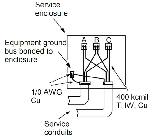
Figure 4. An individual bonding jumper for each raceway. Image used courtesy of Lorenzo Mari
Solution
Bonding jumper size: Enter Table 250.102(C)(1) with conductor size N° 400 kcmil, copper, and get a copper conductor size N° 1/0 AWG as a minimum.
- A single bonding jumper for bonding two or more raceways or cables.
Select from Table 250.102(C)(1), entering the sum of the cross-section areas of the largest ungrounded conductors from each set connected in parallel in each cable or raceway.
Example 3: Compute the minimum supply-side copper bonding jumper size in Figure 5. Each conduit has a bonding bushing with a terminal lug to attach the bonding jumper.
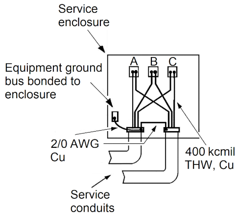
Figure 5. A single bonding jumper for bonding two raceways. Image used courtesy of Lorenzo Mari
Solution
The solution to this example is comparable to Example 1.
Equivalent area for parallel conductors: 400 kcmil + 400 kcmil = 800 kcmil.
Bonding jumper size: Enter Table 250.102(C)(1) with conductor size N° 800 kcmil, copper, and get a copper conductor size N° 2/0 AWG as a minimum.
Example 4: Repeat Example 3, assuming three metal service conduits with 400 kcmil copper conductors connected in parallel.
Solution
Equivalent area for parallel conductors: 400 kcmil + 400 kcmil + 400 kcmil = 1 200 kcmil.
Bonding jumper size: Enter Table 250.102(C)(1) with conductor size N° 1 200 kcmil, copper. The table leads you to Notes 1 and 2.
Note 1 requires an area of not less than 12.5 % of the largest ungrounded supply conductor or equivalent area for parallel conductors.
1 200 kcmil x 0.125 = 150 kcmil
From Table 8, Chapter 9, pick a conductor size N° 3/0 AWG with a cross-section area of 167.8 kcmil.
Section 250.102(D) Sizing Equipment Bonding Jumpers on the Load-Side of Overcurrent Devices
Size the equipment bonding jumper on the load side of an overcurrent device per Table 250.122, as a minimum. Enter the table with the rating or setting of the overcurrent device in the circuit ahead of the equipment.
Sizing bonding jumpers on the load side of an overcurrent device is treated the same as sizing equipment grounding conductors because they perform like tasks.
A single common continuous bonding jumper can connect two or more cables or raceways if sized for the largest overcurrent protective device supplying the circuits.
Example 5: Compute the minimum load-side copper bonding jumper size in Figure 6.
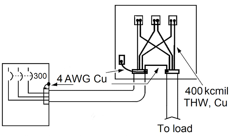
Figure 6. A single bonding jumper on the load side of an overcurrent device. Image used courtesy of Lorenzo Mari
Solution
Enter table 250.122 with 300 A and get a copper conductor size N° 4 AWG.
Example 6: Figure 7 shows three 3-inch conduits containing three parallel sets of 500 kcmil conductors in each conduit for a distribution feeder protected at 1 000 A. Compute the minimum size for three bonding jumpers running from the grounding bushings to the ground bus.
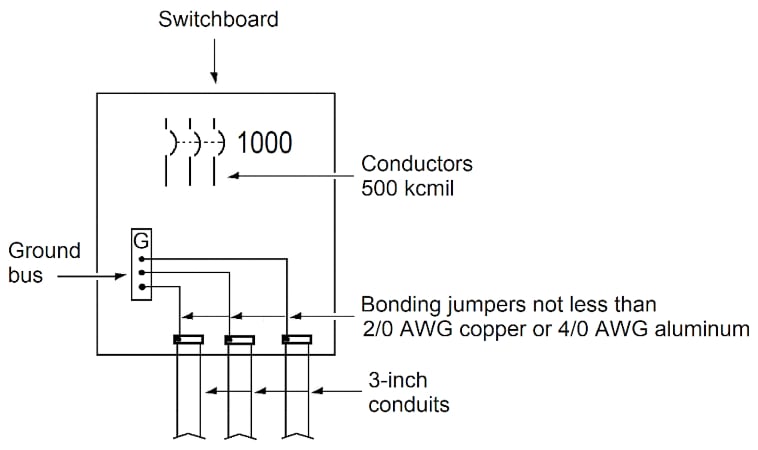
Figure 7. Setup for Example 6. Image used courtesy of Lorenzo Mari
Solution
Enter table 250.122 with 1 000 A and get a copper conductor size N° 2/0 AWG or an aluminum conductor size N° 4/0 AWG.
Example 7: Figure 8 shows three metal conduits exiting a motor control center with three overcurrent protective devices. Find the minimum size bonding jumper looping the conductor through the grounding bushings.
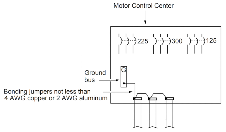
Figure 8. Setup for Example 7. Image used courtesy of Lorenzo Mari
Solution
The largest overcurrent protective device supplying the circuits is 300 A.
Enter table 250.122 with 300 A and get a copper conductor size N° 4 AWG or an aluminum conductor size N° 2 AWG.
Takeaways of Bonding Isolated Grounding Circuits and Sizing Bonding Jumpers
- The interconnection of noncurrent-carrying metal parts must ensure electrical continuity and provide the capacity to carry fault currents safely.
- Isolated grounding circuits help to reduce electrical noise in electronic equipment.
- Bonding jumpers may be built with copper, aluminum, copper-clad aluminum, or another corrosion-resistant material.
- Size the supply-side bonding jumper per Table 250.102(C)(1), as a minimum.
- Bonding jumpers may be individual or continuous (looped through bonding bushings).
- Size the equipment bonding jumper on the load side of an overcurrent device per Table 250.122, as a minimum.
- An equivalent conductor adds the cross-section areas of two or more parallel conductors.
To catch up on Lorenzo Mari’s series on National Electrical Code 2023 Basics: Grounding and Bonding, follow these links:
- National Electrical Code 2023 Basics: Grounding and Bonding Part 1
- National Electrical Code 2023 Basics: Grounding and Bonding Part 2
- National Electrical Code 2023 Basics: Grounding and Bonding Part 3
- National Electrical Code 2023 Basics: Grounding and Bonding Part 4
- National Electrical Code 2023 Basics: Grounding and Bonding Part 5
- National Electrical Code 2023 Basics: Grounding and Bonding Part 6
- National Electrical Code 2023 Basics: Grounding and Bonding Part 7
- National Electrical Code 2023 Basics: Grounding and Bonding Part 8
- National Electrical Code 2023 Basics: Grounding and Bonding Part 9
- National Electrical Code 2023 Basics: Grounding and Bonding Part 10
- National Electrical Code 2023 Basics: Grounding and Bonding Part 11
- National Electrical Code 2023 Basics: Grounding and Bonding Part 12
- National Electrical Code 2023 Basics: Grounding and Bonding Part 13
- National Electrical Code 2023 Basics: Grounding and Bonding Part 14
- National Electrical Code 2023 Basics: Grounding and Bonding Part 15