National Electrical Code 2023 Basics: Grounding and Bonding Part 1
Learn about the general requirements for grounding and bonding in line with the NEC 2023.
The purpose of grounding is the safety of people and property. Grounding and bonding limit overvoltages, stabilize the voltage to the ground during regular functioning, and ease the proper operation of circuit breakers and fuses. All grounding and bonding work must comply with NEC Article 250.

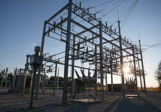
Image used courtesy of Pixabay
What Are Ground and Grounding?
The NEC defines ground as “the earth.”
Grounding is a conductive connection, intentional or accidental, between a circuit or electrical equipment and the ground or some conductive object acting as the ground.
In an airplane, for example, the fuselage acts as the ground.
Correct grounding provides a low-impedance path for ground-fault current.
What is Bonding?
Bonding metal parts entails their connection by a reliable conductor that equalizes their potentials and establishes continuity for ground-fault current.
Figure 1 shows two metal boxes bonded by the metal raceway.

Figure 1. Bonding through a metal raceway. Image used courtesy of Lorenzo Mari
Figure 2 shows two metal boxes connected through a bonding conductor or jumper inside a nonmetallic raceway.

Figure 2. Bonding jumper inside a nonmetallic raceway. Image used courtesy of Lorenzo Mari
Part I of Article 250. General
Section 250.1. This section explains that Article 250 focuses on general grounding and bonding electrical installation requirements, including:
- The grounding of systems, circuits, and equipment.
- Which circuit conductor must be grounded.
- Where to locate the grounding connections.
- The characteristics of the electrodes and grounding and bonding conductors.
- How to ground and bond.
- When grounding may replace guards, isolation, or insulation.
Section 250.4. This section portrays the reasons for grounding and bonding electrical systems and equipment and defines overall performance objectives – as an introduction to the specific rules detailed in the remainder of Article 250. It includes grounded and ungrounded systems.
Section 250.4(A) Grounded systems.
- System grounding is the connection to the ground – solidly or through impedance – of current-carrying conductors – e.g., the neutral point of a wye-connected transformer and the phase on a corner-grounded delta connection.
The purposes are to:
◦ limit overvoltages due to lightning, line surges, or accidental contacts with higher-voltage lines
◦ stabilize the voltage to earth during regular operation
Limiting the conductor length and avoiding unnecessary bends and loops will reduce the impedance of the fault-current path, facilitating the operation of the overcurrent protective devices or ground detectors for high-impedance grounded systems.
The routing of the bonding and grounding electrode conductors must not disturb the permanent parts of the installation.
The Standard NFPA 780-2020 gives directions regarding grounding and bonding connections in lightning protection systems.
- Equipment grounding is the connection to the ground of non-current-carrying conductive materials – e.g., cable trays, metallic conduits, junction boxes, transformer casings, and motor frames.
The purpose is to limit the conductive material voltage to the ground.
- Equipment bonding is the connection between non-current-carrying conductive materials and the supply source.
The purpose is to establish an effective ground-fault current path.
This practice will facilitate the operation of overcurrent protective devices or ground detectors.
- The electrically conductive material and other equipment bonding connect non-current-carrying conductive materials that may become energized to the supply source.
The purpose is to establish an effective ground-fault current path.
Potential differences may harm people contacting two surfaces with different potentials simultaneously. Bonding equalizes the potentials between the surfaces, averting the hazard.
Figure 3 shows a typical grounding and bonding arrangement for a single-phase, 3-wire connection fed from the utility transformer.

Figure 3. A typical single-phase, 3-wire grounding system. Image used courtesy of Lorenzo Mari
At the service equipment, the service grounded conductor connects to the grounding electrode via the grounding electrode conductor.
The bridge between the equipment grounding bus and the neutral or grounded bus via the main bonding jumper provides:
- A ground reference to the electrical system’s exposed, non-current-carrying conductive materials.
- A path back to the transformer (the supply source) through the grounded service conductor for ground-fault currents.
Making another connection from the grounded conductor on the utility transformer to a separate grounding electrode is typical.
Section 250.4(A)(5) requires connecting the electrical equipment, wiring, and electrically conductive material expected to become energized, forming a low-impedance circuit – an effective ground-fault current path. This circuit enables the operation of the overcurrent devices or ground detectors.
The low-impedance circuit must carry the maximum ground-fault current from any point where a ground fault arises to the electrical source.
The NEC considers that the earth is not an effective ground-fault current route.
The quantity of current flowing into the earth back to the supply source during a ground fault depends on the circuit voltage and the earth’s resistance.
Since the earth’s resistance is high, an arrangement using the earth as the only return path to the supply source will not carry enough current to clear the fault, posing a dangerous voltage between the metal parts and the ground. Hence, such an arrangement is not an effective ground-fault current path.
For example, a 120 V circuit grounded through a 25 Ω ground rod will produce a ground-fault current of 120 V/25 Ω = 4.8 A back to the supply source. This low current magnitude will likely not trip the circuit breaker or melt the fuses.
Section 250.4(B) Ungrounded systems.
- Equipment grounding is the connection of non-current-carrying conductive materials to the earth.
The purpose is to limit the voltage to the ground impressed by lightning or accidental contact with higher-voltage lines.
- Equipment bonding connects the non-current-carrying conductive materials, and the supply system grounded equipment.
The purpose is to establish a low-impedance path to carry the maximum available ground-fault current.
- The electrically conductive material and other equipment bonding is the connection to the supply system grounded equipment of the non-current-carrying conductive materials that may become energized.
The purpose is to establish a low-impedance path capable of carrying the maximum ground-fault current.
Section 250.4(B)(4) requires the connection of all the wiring, electrical equipment, and other electrically conductive material that may become energized to establish a low-impedance path to the power source. This practice facilitates the operation of the overcurrent protective devices in the event of a second ground fault in another phase.
The earth is not an effective fault-current path.
Section 250.118(5)(d) poses conditions to use a flexible metal conduit as an equipment grounding conductor. It prohibits using the flexible metal conduit as an equipment grounding conductor if its length exceeds 1.8 m. This situation requires using a wire-type equipment grounding conductor or a bonding jumper. Figure 4 shows an effective ground-fault current path.

Figure 4. A flexible metal conduit with internal wire-type EGC for grounding and bonding. Image used courtesy of Lorenzo Mari
Figures 5 and 6 show incorrect applications of the flexible metal conduit as an equipment grounding conductor. The fault current may take random paths back to the source, with the resulting risks of fire and electrocution – these are not effective ground-fault current paths.

Figure 5. Misapplication of a flexible metal conduit as equipment grounding conductor. Image used courtesy of Lorenzo Mari

Figure 6. Misapplication of a flexible metal conduit as equipment grounding conductor. Image used courtesy of Lorenzo Mari
Note the arrangements in figures 5 and 6 do not comply with Section 250.118(5).
Section 250.6. This section covers the objectionable currents.
250.6(A) affirms that grounding and bonding conductors, circuit conductors, SPDs, surge arresters, and non-current-carrying metal parts must prevent objectionable currents.
Objectionable currents flow permanently on the grounding and bonding paths due to the improper connection of conductors and equipment.
One example of an incorrect circuit arrangement is having the neutral or grounded conductor connected to the ground at several points, not only at the service equipment.
Figure 7 shows an objectionable current through the equipment grounding conductor when the grounded conductor has an additional grounding connection.

Figure 7. Objectionable current. Image used courtesy of Lorenzo Mari
The ungrounded conductor supplies the load current. The load current returns to the source via the grounded conductor and the rest of the grounding and bonding system, including the equipment grounding conductor, metallic water pipes, metallic gas pipes, metal raceways, and building steel – generating potential differences to the ground.
Section 242.30 permits the interconnection between the grounded conductor and the equipment grounding conductor by the regular operation of a surge protective device (SPD) during a surge.
Note that the grounded conductor requires insulation despite being grounded. Otherwise, its current would pass to the metallic structures it contacts, creating objectionable currents.
250.6(B) permits alterations of the grounding connections to stop the objectionable currents. First, confirm that it is objectionable. If that’s the case, the NEC allows one or more of the following changes:
- Remove one or more grounding or bonding connections – but not all.
- Change the position of the grounding or bonding connections.
- Break the continuity of the conductor or path producing the objectionable current.
- Adopt other corrective measures – only if they are acceptable to the authority having jurisdiction.
250.6(C) states that currents through grounding and bonding conductors under abnormal conditions – like a ground fault – and those resulting from required grounding and bonding connections are not objectionable.
250.6(D) indicates that electronic equipment cannot be installed on AC systems or branch circuits lacking equipment grounding conductors. Currents introducing electromagnetic interference or data errors in electronic equipment are not objectionable.
250.6(E) permits using a listed isolator device to block objectionable DC ground currents – from cathodic protection systems – in the equipment grounding conductor path. This way, the ground-fault current return path will perform correctly for AC while blocking DC.
Section 250.8. This section covers the permitted and not permitted methods to connect grounding electrode conductors, equipment grounding conductors, and bonding jumpers.
250.8(A) lists the permitted methods as follows:
- Pressure connectors.
- Terminal bars.
- Pressure connectors if listed as grounding and bonding equipment.
- Exothermic welding.
- Machine screw-type fasteners.
- Thread-forming machine screws.
- Connections part of a listed assembly.
- Other listed methods.
Figures 8, 9, and 10 show three methods permitted per section 250.8(A).

Figure 8. Listed pressure connectors. Image used courtesy of Lorenzo Mari

Figure 9. Listed compression grounding connector. Image used courtesy of Burndy.

Figure 10. Exothermic weld. Vertical through cable to vertical steel surface. Image used courtesy of Burndy.
250.8(B) highlights soldering as a not permitted method.
Section 250.10. This section requires enclosing in metal, wood, or equivalent protective covering all ground clamps and other fittings exposed to physical damage.
Section 250.12. This section requires cleaning all contact surfaces on the equipment to be grounded or bonded.
Removing nonconductive coatings from threads and other contact surfaces – such as paints, lacquers, enamels, or the like – is vital to obtain good electrical continuity. It is also valid the use of fittings designed to make such removal unnecessary.
Key Takeaways of Grounding and Bonding
- Grounding and bonding limit overvoltages, stabilize the voltage to the ground during regular operation and improve the performance of overcurrent protective devices.
- The grounding path from circuit equipment and metal enclosures to the supply source must be continuous, not subject to damage, and capable of carrying the fault currents imposed on them.
- The impedance of the fault-current path must be low enough to generate sufficient fault current to actuate the overcurrent devices protecting the circuit.
- The earth is not an effective fault-current path.
- The arrangement of the electric system must prevent objectionable currents from flowing through the grounding and bonding paths.
- Grounding and bonding equipment must be adequately connected and located where it will not undergo damage.
- Good electrical continuity in the contact surfaces is a must.


