Facebook
 Google
 GitHub
 Linkedin
National Electrical Code 2023 Basics: Grounding and Bonding Part 7
Learn about the rules regarding multiple separately derived systems, bonding to metallic parts, ungrounded systems, and outdoor sources.
To catch up on Lorenzo Mari’s series on grounding and bonding, please follow these links:
- National Electrical Code 2023 Basics: Grounding and Bonding Part 1
- National Electrical Code 2023 Basics: Grounding and Bonding Part 2
- National Electrical Code 2023 Basics: Grounding and Bonding Part 3
- National Electrical Code 2023 Basics: Grounding and Bonding Part 4
- National Electrical Code 2023 Basics: Grounding and Bonding Part 5
- National Electrical Code 2023 Basics: Grounding and Bonding Part 6

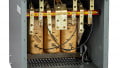
Image used courtesy of Burndy
The NEC permits using a common grounding electrode conductor for several separately derived systems. Bonding to metal parts in the area protects people against dangerous voltages. Ground outdoor sources at their location.
NEC Section 250.30(A)(6) deals with the grounding electrode conductor when having multiple separately derived systems. This section permits using a common grounding electrode conductor for several separately derived systems instead of installing separate conductors from each system to the grounding electrode.
The common conductor connects each grounded conductor to the grounding electrode. Each separately derived system has a tap connecting the grounded conductor to the common conductor. Connect the tap along with the system bonding jumper. See Figure 1.
This section is like an exception to Section 250.30(A)(5).

Figure 1. Common grounding electrode conductor when having multiple separately derived systems. Image used courtesy of Lorenzo Mari
250.30(A)(6)(a) lists the permitted grounding electrode conductors as follows:
- A wire-type conductor of a size greater than or equal to N° 250 kcmil aluminum or N° 3/0 AWG copper.
The minimum size assures that the common grounding electrode conductor can hold multiple separately derived systems.
- An interior metal water pipe connected to an underground water pipe electrode not farther than 1.52 m from the building’s entry.
- The building's metal frame, complying with 250.68(C)(2) or connected to the grounding electrode system by a conductor of size greater than or equal to N° 3/0 AWG copper or N° 250 kcmil.
Section 250.68(C)(2) permits using the building’s structural frame to connect the components of a grounding electrode system.
250.30(A)(6)(b) requires sizing the tap conductors by Section 250.66 based on the ungrounded conductor’s size – use Table 250.66.
There are exceptions to (a) and (b) above for the grounding electrodes specified in sections 250.66(A), (B), or (C).
Example 1. Figure 2 shows ungrounded conductor sizes for three separately derived systems (SDS). Determine the minimum sizes for the individual tap conductors and the common grounding electrode conductor. All conductors are aluminum or copper-clad aluminum.

Figure 2. Setup for Example 1. Image used courtesy of Lorenzo Mari
Answer:
Size the common grounding electrode conductor per Section 250.30(A)(6)(a) and the taps by Section 250.30(A)(6)(b).
SDS 1. 2 x 500 kcmil = 1 000 kcmil. Enter Table 250.66, aluminum column, with size N° 1 000 kcmil. Minimum tap conductor size = N° 4/0 AWG aluminum.
SDS 2. Enter Table 250.66, aluminum column, with size N° 3/0 AWG. Minimum tap conductor size = N° 4 AWG aluminum.
SDS 3. Enter Table 250.66, aluminum column, with size N° 500 kcmil. Minimum tap conductor size = N° 1/0 AWG aluminum.
The minimum common grounding electrode conductor size is N° 250 kcmil aluminum.
250.30(A)(6)(c) specifies the methods to connect the tap conductor(s) to the common grounding electrode conductor as follows:
- Make the connections at a reachable location.
- Connectors listed as grounding and bonding equipment.
Figure 3 shows a listed copper compression connector.

Figure 3. Compression Grounding C-TAP Connector. Image used courtesy of Burndy
- A copper or aluminum busbar greater than or equal to 6 mm x 50 mm and long enough to accommodate all terminations. Use listed connectors.
Figure 4 shows a copper busbar for grounding.
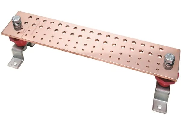
Figure 4. Copper Ground Busbar. Image used courtesy of Burndy
- Exothermic weld connections.
Figure 5 shows an exothermic weld connection.
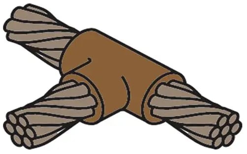
Figure 5. Exothermic weld connection. Image used courtesy of Burndy
- The common grounding electrode conductor will not have splices or joints.
Section 250.30(A)(7) requires installing the grounding electrode conductors per 250.64(A), (B), (C), and (E).
- (A) Requirements for using aluminum or copper-clad aluminum as grounding electrode conductors. The grounding electrode conductor must be copper if it is external to the building or the enclosure and terminated within 450 mm of the earth's surface.
- (B) The grounding electrode conductor or its enclosure must be firmly tied to the supporting surface and protected from physical damage.
- (C) The grounding electrode conductor must be unbroken, with some exceptions and permissions.
- (E) Bond the ferrous metal raceways, enclosures, and cable armor to make them electrically continuous. Non-ferrous metal raceways, enclosures, and cable armor need not be electrically continuous.
Section 250.30(A)(8) requires connecting the structural steel and metal pipes to the grounded conductor of the separately derived systems, per Section 250.104(D). Section 250.104 rules the bonding of exposed structural metal and piping systems.
This practice avoids permanent dangerous voltages in metal parts in the area supplied by a separately derived system – allowing fast removal of ground faults.
Section 250.30(B) Ungrounded systems. This section covers ungrounded, separately derived systems.
Section 250.30(B)(1) requires a grounding electrode conductor connecting the metal enclosures to the grounding electrode.
Size the conductor per Section 250.66, based on the largest ungrounded conductor size, and connect it at any point between the source and the first disconnecting means.
Figure 6 shows the grounding electrode conductor and grounding electrode connections for an ungrounded separately derived system.

Figure 6. Grounding and bonding connections for metal enclosures in an ungrounded system. Image used courtesy of Lorenzo Mari
The connection must comply with Section 250.30(C) for outdoor sources.
The combination of grounding electrode conductor and grounding electrode establishes a ground reference for the non–current-carrying metal enclosures supplied by the ungrounded separately derived system. This connection is also the way to ground all equipment grounding conductors.
Section 250.30(B)(2) requires the grounding electrode to comply with Section 250.30(A)(4) except for portable and vehicle-mounted generators, as permitted in Section 250.34.
Section 250.30(B)(3) involves the connection of a supply-side bonding jumper between the source and the first disconnecting means of the separately derived system, in compliance with 250.30(A)(2).
Section 250.30(C) Outdoor source. This section entails the connection of one or more grounding electrodes to sources external to the building or structure. The grounding electrode(s) must comply with Section 250.50 and all the installation with sections 250.30(A) or 250.30(B) for grounded and ungrounded systems, respectively.
Place the system bonding jumper at the outdoor location when applying this rule.
The rules in this section help to protect against transient overvoltages originating externally and unintended contact between conductors of different voltages.
Figure 7 shows the grounding and bonding connections for a grounded system.

Figure 7. Grounding and bonding connections for a grounded system located outdoors. Image used courtesy of Lorenzo Mari
Figure 8 shows the grounding and bonding connections for a grounded system.

Figure 8. Grounding and bonding connections for an ungrounded system located outdoors. Image used courtesy of Lorenzo Mari
Figure 9 shows the grounding and bonding connections for an ungrounded outdoor system without secondary overcurrent protection.

Figure 9. Grounding and bonding connections for an ungrounded outdoor system without secondary overcurrent protection. Image used courtesy of Lorenzo Mari
The exception directs to sections 250.36 (up to 1 kV) and 250.187 (above 1 kV) for the rules covering the grounding electrode conductor connections of neutrals grounded through an impedance.
Key Takeaways of Multiple Separately Derived Systems
- Several separately derived systems may use a common grounding electrode conductor to connect to the grounding electrode.
- Bond all the structural steel and metal pipes to the grounded conductor to avoid dangerous voltages in metal parts.
- In ungrounded systems, connect the metal enclosures to the grounding electrode employing a grounding electrode conductor.
- Outdoor sources require a connection to the grounding electrodes–protecting against transient overvoltages or contact with higher voltage conductors.
Featured image used courtesy of Adobe Stock