Facebook
 Google
 GitHub
 Linkedin
Reverse Recovery Charge Is Not a Constant
Reverse recovery charge, QRR, is one of those parameters most power engineers know well. It appears prominently in MOSFET datasheets, it finds its way into switching-loss equations, and it is often used to compare devices when efficiency matters. The problem is not that QRR is unimportant; it is that it is commonly misunderstood.
This article is published by EEPower as part of an exclusive digital content partnership with Bodo’s Power Systems.
In modern power converters, particularly high-frequency, hard-switched designs, QRR does not behave like a fixed device constant. Instead, it depends strongly on how long the MOSFET’s body diode conducts current before the device is reverse-biased. In systems where dead time is aggressively minimized, the actual reverse recovery charge involved in switching can be far lower than the datasheet value. This effect becomes increasingly pronounced in MOSFETs rated above 100V.

Image used courtesy of Pexels
These trends are consistently reflected in analytical modeling, device-level simulations, and controlled laboratory measurements spanning multiple voltage classes. Recognizing QRR as a time-dependent quantity rather than a static number allows designers to model losses more accurately, optimize dead time with confidence, and recover efficiency that is often left unrealized.
Where Does Reverse Recovery Really Come From?
The source of reverse recovery is the intrinsic body diode present in most vertical silicon power MOSFETs. In half-bridge and synchronous converter topologies, this diode conducts current during the brief interval when both MOSFETs are off. That interval is typically set by the system’s dead time.
While the diode is forward-biased, minority carriers are injected into the MOSFET’s drift region. When the complementary MOSFET turns on, and a reverse voltage is applied, the stored carriers must be removed before the diode can block. They are eliminated either through recombination within the silicon or by being swept out as a reverse current spike. This transient process is what is referred to as reverse recovery.
Reverse recovery behavior is commonly summarized using three parameters: reverse recovery charge, QRR; peak reverse recovery current, IRM; and reverse recovery time, trr. Of these, QRR is most often used as a proxy for switching loss. However, the way QRR is typically measured and reported obscures its behavior in real-world applications.
Why Does the Datasheet QRR Often Misrepresent Reality?
Industry standards measure QRR after the body diode has been conducting long enough to reach steady-state forward conduction. At that point, minority-carrier storage has fully saturated, yielding a worst-case value for comparison.
The difficulty is that modern converters rarely operate under these conditions. In high-performance systems, dead times are routinely pushed into the tens of nanoseconds. High-frequency SMPS designs often operate with dead times between 20ns and 100ns, Class-D audio amplifiers reduce dead time to tens of nanoseconds to minimize distortion, and many motor drives are similarly optimized for efficiency.
At these time scales, the body diode never reaches steady-state conduction. The amount of stored charge is therefore much lower than the datasheet QRR value, sometimes by a wide margin. Using steady-state QRR to estimate switching losses in these systems can significantly overstate the real loss contribution.
Stored Charge Accumulates Over Time, Not Instantly
The reason QRR is not constant is due to the physics of minority-carrier storage. When the body diode begins conducting, the stored charge does not appear instantaneously. Instead, it builds up gradually, following an exponential curve governed by the device’s minority-carrier lifetime.
For very short body diode conduction times, only a small amount of charge is injected into the drift region. As conduction time increases, stored charge rises exponentially until it approaches a saturation level. That saturation level corresponds to the steady-state QRR reported in datasheets. When the conduction interval is short relative to the minority carrier lifetime, only a fraction of that charge is present.
This behavior means that QRR is fundamentally a function of body diode conduction time. Treating it as a single fixed number ignores the operating regime in which many modern converters actually run.
Why Does the Voltage Rating Amplify the Effect?
The time dependence of QRR becomes more pronounced as the MOSFET voltage rating increases. Higher-voltage devices require longer drift regions to support their breakdown voltage. The larger silicon volume takes longer to fill with injected carriers during diode conduction.
As a result, higher-voltage MOSFETs require longer conduction intervals to reach full-charge saturation, even if their intrinsic carrier lifetime is similar to that of lower-voltage devices. In practice, this means that short dead times reduce effective QRR far more dramatically in 150V, 200V, and higher-voltage MOSFETs than in lower-voltage parts.
This explains why designers working with higher-voltage silicon often see a disconnect between datasheet QRR values and observed switching behavior when dead time is minimized.
What Simulation Shows About QRR Versus Time?
To better understand how this time dependence manifests across voltage classes, device-level simulations were used to examine reverse recovery behavior under controlled conditions. To explore this behavior in detail, charge-balanced silicon MOSFETs rated at 150V, 200V, and 650V were evaluated using mixed-mode TCAD simulations, representing modern low-loss device architectures commonly used in high-performance power converters, including designs such as iDEAL Semiconductor’s SuperQ™ technology. The simulation data for various voltage class MOSFETs is shown in Figure 1. For each voltage case, the body diode conduction time was swept from tens of nanoseconds to several hundred nanoseconds, and the resulting reverse recovery charge was extracted.
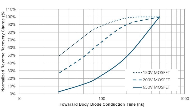
Figure 1. TCAD simulation data of QRR vs Ton. Image used courtesy of Bodo’s Power Systems [PDF]
The results reveal a clear and consistent trend. QRR increases exponentially with body diode conduction time, and the time required to approach saturation increases with voltage rating. At a conduction time of approximately 30ns, the effective QRR was reduced by roughly 30 percent in the 150V device and by about 60 percent in the 200V device. In the 650V device, QRR decreased by more than 90% relative to its long-conduction value. Even at 500ns, the highest-voltage device had not yet fully reached steady-state saturation.
For systems operating with dead times below 100ns, these differences are not subtle; they fundamentally change how reverse recovery should be modeled.
Measurement Confirms the Trend
Simulation alone is not sufficient. To validate the results, a 200V MOSFET was tested using a platform that allowed independent control of forward conduction current, switching slew rate, and body diode conduction time.
When the diode was allowed to conduct for a long interval, the measured QRR closely matched the datasheet value, confirming that the test conditions reproduced conventional characterization conditions. As the conduction time was reduced towards 30ns, the measured QRR decreased steadily, following the same exponential trend predicted by simulation.
The strong agreement between simulation and measurement confirms that the reverse recovery charge is inherently transient and strongly dependent on conduction time, rather than a fixed property of the device.
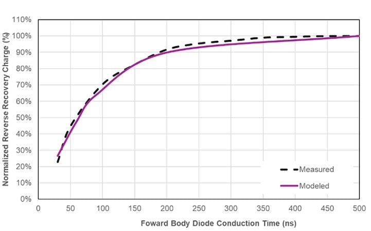
Figure 2. Measured and Modeled MOSFET QRR versus tBDC. Image used courtesy of Bodo’s Power Systems [PDF]
Dead Time Versus Body Diode Conduction Time
One source of persistent confusion in system design is the difference between programmed dead time and actual body diode conduction time. Dead time is defined digitally by the PWM controller, but the interval during which the body diode actually conducts depends on a combination of analog effects. These include driver propagation delays, external and internal gate resistance, MOSFET capacitances, and threshold voltage variation.
In practice, the body diode conduction interval is often significantly shorter than the programmed dead time. As a result, many systems already operate in a regime where effective QRR is well below the datasheet value, even if designers are not explicitly accounting for it. Understanding this distinction is essential for optimizing dead time and improving efficiency.
When QRR Causes Loss And When It Does Not?
Another important nuance is that QRR does not create a loss in the MOSFET that stores the charge. The loss occurs when the reverse recovery current is forced through a switching device during its turn-on transition. In synchronous buck converters, this mechanism can significantly increase switching loss in the control MOSFET. In other topologies, such as phase-shifted full-bridge converters, reverse recovery may occur without incurring a comparable switching loss penalty.
This makes the impact of QRR highly application-dependent and reinforces the need to evaluate reverse recovery behavior in the context of the specific topology and operating mode
Why is Excessive Dead Time Often Unnecessary?
To ensure shoot-through immunity, many designs use dead times on the order of hundreds of nanoseconds or more. However, timing analysis via Monte Carlo analysis shows that the actual variation caused by component tolerances is often far smaller than assumed. Reducing dead time shortens body diode conduction, lowers diode conduction loss, and significantly reduces effective QRR, provided the system remains outside the shoot-through region.
System-level measurements, as shown in Figure 3, typically show a clear minimum in total loss as dead time is reduced. Operating near this minimum allows designers to capture efficiency gains that are otherwise masked by conservative assumptions.
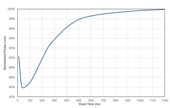
Figure 3. Normalized Power Loss versus Dead Time. Image used courtesy of Bodo’s Power Systems [PDF]
Time to Rethink How QRR Is Specified
Treating QRR as a single worst-case number made sense when switching speeds were slower and dead times were longer. In modern converters, it no longer reflects real operating conditions. Presenting QRR as a function of body diode conduction time would enable more accurate loss prediction, better dead-time optimization, clearer device comparison, and higher overall system efficiency.
A practical implication of this behavior is that a single datasheet QRR value may be insufficient. A more useful approach would be to present QRR as a function of body diode conduction time, or to specify QRR at multiple defined conduction intervals. This would allow designers to accurately model losses and optimize dead time based on real operating conditions rather than worst-case assumptions.
Conclusion
Reverse recovery charge in power MOSFETs is not a static parameter. It is a time-dependent quantity governed by minority carrier lifetime, device geometry, and the duration of body diode conduction. Both simulation and measurement show that in fast-switching systems, effective QRR can be far lower than datasheet values, particularly in higher-voltage devices.
Recognizing this behavior allows designers to move beyond overly conservative loss estimates and unlock the efficiency gains already present in their systems. As switching speeds continue to increase and dead times shrink, understanding the time-dependent nature of reverse recovery becomes essential for accurately interpreting device behavior in modern power system design. In this context, both QRR characterization and designers’ thinking about it must evolve as well.
This article originally appeared in Bodo’s Power Systems [PDF] magazine.