National Electrical Code 2023 Basics: Grounding and Bonding Part 8
Learn the grounding and bonding rules when powering two or more buildings or structures in the same area with a single service.
To catch up on Lorenzo Mari’s series on National Electrical Code 2023 Basics: Grounding and Bonding, follow these links:
- National Electrical Code 2023 Basics: Grounding and Bonding Part 1
- National Electrical Code 2023 Basics: Grounding and Bonding Part 2
- National Electrical Code 2023 Basics: Grounding and Bonding Part 3
- National Electrical Code 2023 Basics: Grounding and Bonding Part 4
- National Electrical Code 2023 Basics: Grounding and Bonding Part 5
- National Electrical Code 2023 Basics: Grounding and Bonding Part 6
- National Electrical Code 2023 Basics: Grounding and Bonding Part 7
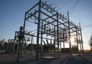
NEC’s Section 250.32 regulates the connections of the grounding electrode system, grounding electrode conductor, and equipment grounding conductor when a single service supplies power to two or more buildings nearby.

Image used courtesy of Pixabay
National Electrical Code Section 250.32
Section 250.32 covers the grounding and bonding of buildings or structures supplied by feeders or branch circuits.
Section 250.32(A) Grounding Electrode System and Conductor
This section contains the section’s basic rule and one exception. The basic rule requires the bonding of all grounding electrodes, installed as per Part III, at the building or structure supplied by a feeder or branch circuit–to form the grounding electrode system–and provide a grounding electrode conductor.
Figure 1 shows Building 1 grounded per Section 250.24 and Building 2 with the equipment grounding bus bonded to the building’s grounding electrode system.

Figure 1. Grounding electrode system obligatory at feeder-supplied Building 2. Image used courtesy of Lorenzo Mari
Ground the exposed non-current-carrying metal parts of electrical equipment through equipment grounding connections to the equipment grounding bus located at the building disconnecting means.
The feeder or branch circuit may be overhead or underground.
The exception to Section 250.32(A) bypasses the requirement for a separate grounding electrode system and grounding electrode conductor for each building or structure. It applies when only one branch circuit supplies the building or structure and includes an equipment grounding conductor to ground all non-current-carrying metal parts of equipment.
The exception accepts a multiwire branch circuit as a single circuit.
A small residential garage with one lighting outlet and a receptacle qualifies for this exception (see Figure 2).

Figure 2. No connection to the grounding electrode system is required when a single branch circuit supplies the second building and includes an equipment grounding conductor. Image used courtesy of Lorenzo Mari
Table 1 shows examples of single-branch circuits.
Table 1. Typical single-branch circuits. Image used courtesy of Lorenzo Mari
|
DESIGNATION |
PHASES |
CURRENT-CARRYING CONDUCTORS |
|
120 V, 2-wire |
1 |
2 |
|
120/240 V, 3-wire |
1 |
3 |
|
208Y/120 V, 4-wire |
3 |
3 or 4 |
Provide and connect a grounding electrode conductor and grounding electrode system when two or more 2-wire or multi-wire branch circuits supply the building or structure.
The rules for grounding and bonding buildings or structures supplied by feeders or branch circuits apply to grounded and ungrounded systems.
Section 250.32(B) Grounded Systems
This section covers grounded power supplies.
250.32(B)(1) Supplied by a Branch Circuit or Feeder
This section requires an equipment grounding conductor in the supply conductors. Connect the equipment grounding conductor to the building’s grounding electrode and disconnecting means.
Connect all structures, equipment, and frames requiring grounding or bonding to the equipment grounding conductor–sized per Section 250.122 (see Figure 3).

Figure 3. Supply to a second building, including an equipment grounding conductor. Image used courtesy of Lorenzo Mari.
It is prohibited to connect the grounded conductor to the grounding electrode or equipment grounding conductor–to prevent the flow of objectionable load currents on metal parts. The grounded conductor must be isolated from the grounding electrode equipment and grounding conductor at the building supplied by the feeder or branch circuit.
Installing an equipment grounding conductor will keep the load current in the grounded conductor. Grounding the equipment employing the grounded conductor may generate abnormal paths for load current along metal piping, metal cable sheaths or shields, metal raceways, and ductwork. Yet, Exception N°1 to Section 250.32(B)(1) permits re-grounding the feeder’s grounded conductor supplying Building 2 in installations complying with previous editions of the NEC–before 2008.
The grounded conductor will serve as a ground-fault return path in existing installations meeting all the following conditions (see Figure 4):
- The supply circuit does not include an equipment grounding conductor.
This requirement includes a wiring method acting as an equipment grounding conductor, such as a rigid metal conduit. In such a case, a system grounding connection will create a parallel path for the grounded conductor current–the conduit will most likely contain the grounded conductor.
- There are no continuous metallic paths connecting the buildings’ grounding systems.
An example is a shared metallic water piping between the buildings–making the water pipes parallel conductors.
- There is no equipment ground-fault protection on the supply side.
A line-to-ground fault would return to the source through the grounded conductor, looking as load current to the ground-fault protective device, averting its purpose.

Figure 4. Grounding arrangement with the grounded conductor bonded to the grounding electrode – in existing wiring systems only. Image used courtesy of Lorenzo Mari.
The grounded conductor must perform as an equipment grounding conductor and a neutral. Then, its size must not be smaller than the larger of:
- The calculated neutral load per Section 220.61.
- The minimum equipment grounding conductor size per Section 250.122.
250.32(B)(2) Supplied by a Separately Derived System
The grounding and bonding requisites for a building supplied by a separately derived system depend on the position of the overcurrent protective devices.
250.32(B)(2)(a)
With overcurrent protection where the conductors originate, when the separately derived system contains overcurrent protection, the wiring must comply with Section 250.32(B)(1)–the supply conductors must include an equipment grounding conductor to serve as the ground-fault return path.
An example is a generator with overcurrent protective devices installed to protect the feeder–the feeder must include an equipment grounding conductor.
Attach the equipment grounding conductor to the grounding electrode and the building disconnecting means–where fitted. This practice is also a requirement for feeders originating in a separate building.
250.32(B)(2)(b)
Without overcurrent protection where the conductors originate, the installation must comply with Section 250.30(A).
A typical case is an outdoor transformer without overcurrent protection, supplying a system–as permitted by Section 240.21(C)(4). This installation must be grounded and bonded per Section 250.30(A).
A supply-side bonding jumper connected to the disconnecting means and the grounding electrode will complete the ground-fault current path between the source and the building supplied.
Section 250.32(C) Ungrounded Systems
This section covers ungrounded power supplies.
250.32(C)(1) Supplied by a Branch Circuit or Feeder
This section requires installing an equipment grounding conductor with the supply conductors and connecting it to the disconnecting means and the grounding electrode in the additional building. See Figure 5.

Figure 5. Grounding arrangement for an ungrounded system supplied by a feeder or branch circuit. Image used courtesy of Lorenzo Mari.
250.32(C)(2) Supplied by a Separately Derived System
250.32(C)(2)(a)
With overcurrent protection where the conductors originate. When the separately derived system contains overcurrent protection, the installation must comply with Section 250.32(C)(1).
250.32(C)(2)(b)
Without overcurrent protection where the conductors originate. The installation must comply with Section 250.30(B).
A connection to the grounding electrode is required every time an ungrounded system supplies the second building–bond the grounding electrode to the ground bus in the disconnect.
Bond the equipment grounding conductor going to the second building to any existing grounding electrode, such as the building’s metal frame and the metallic water pipe.
A supply-side bonding jumper connected to the disconnecting means and the grounding electrode will complete the ground-fault current path between the source and the building supplied.
Section 250.32(D) Main Disconnecting Means Located in Another Building
This section covers the grounding arrangement when the main disconnecting means for the feeder is located elsewhere from the building being supplied – for example, in the building where the feeder begins.
This section links the concepts of Section 250.32 with the disconnect requirements of Section 225.31(B), Exception N°1, and Exception N°2. These exceptions deal with industrial facilities under single management with buildings lacking local disconnects and keeping safe switching procedures maintained by qualified personnel.
The rules also consider outdoor generator sets located remotely, as stated in sections 700.12(D)(4), 701.12(D)(3), and 702.12.
Providing a grounding electrode conductor is still a must. A few specific requirements regarding grounding and bonding are:
Do not bond the grounded conductor to the panel enclosure, equipment grounding bus, grounding electrode, non-current-carrying metal parts of equipment, or equipment grounding conductor at the building supplied.
Run an equipment grounding conductor with the supply conductors.
Connect the equipment grounding conductor to non-current-carrying metal parts of equipment, structural metal frames, interior metal piping systems, and a new or existing grounding electrode system at the second building– unless it is supplied by only one branch circuit.
Make the connection between the grounding electrode and the equipment grounding conductor in a panelboard, junction box, or similar enclosure located either inside or outside of the building supplied. Place the enclosure at a point nearest to the supply conductor’s entrance.
Figure 6 shows the grounding connections for a separate building supplied by more than one branch circuit, and another building contains the disconnecting means.

Figure 6. Grounding arrangement when a separate building contains the disconnecting means. Image used courtesy of Lorenzo Mari.
Section 250.32(E) Grounding Electrode Conductor
This section rules the grounding electrode conductor sizing when located in buildings supplied by feeders, branch circuits, or both, as follows:
Size the grounding electrode conductor following Table 250.66. Enter the table with the size of the largest ungrounded feeder or branch circuit conductor supplying the building or structure.
Table 250.66 shows N° 3/0 AWG copper or N° 250 kcmil aluminum as the maximum required size (for ungrounded conductor sizes over N° 1 100 kcmil copper or N° 1 750 kcmil aluminum).
Example: Compute the grounding electrode conductor size required for a second building disconnect supplied with a N° 4/0 AWG copper feeder.
Answer: Enter Table 250.66 with conductor size N° 4/0 AWG copper and read grounding electrode conductor size N° 2 AWG copper or N° 1/0 AWG aluminum.
Key Takeaways of Grounding and Bonding
- NEC Section 250.32 addresses the grounding and bonding of two or more buildings or structures nearby with only one service.
- Buildings and structures supplied by feeders or branch circuits require a grounding electrode system and a grounding electrode conductor.
- The preceding paragraph is not required when a single branch circuit supplies the building or structure.
- There are similar rules for grounded and ungrounded systems. Take care in their application as they are similar but not identical.
- The grounding and bonding requirements for a building fed by a separately derived system, in grounded and ungrounded systems, depend on the position of the overcurrent protective devices.
- There are several conditions for it to be acceptable to have the primary disconnect device in a building other than the one served.
- Table 250.66 allows the sizing of the grounding electrode conductor.


