Facebook
 Google
 GitHub
 Linkedin
National Electrical Code 2023 Basics: Grounding and Bonding Part 11
Learn about grounding electrode systems and conductors.
To catch up on Lorenzo Mari’s series on National Electrical Code 2023 Basics: Grounding and Bonding, follow these links:
- National Electrical Code 2023 Basics: Grounding and Bonding Part 1
- National Electrical Code 2023 Basics: Grounding and Bonding Part 2
- National Electrical Code 2023 Basics: Grounding and Bonding Part 3
- National Electrical Code 2023 Basics: Grounding and Bonding Part 4
- National Electrical Code 2023 Basics: Grounding and Bonding Part 5
- National Electrical Code 2023 Basics: Grounding and Bonding Part 6
- National Electrical Code 2023 Basics: Grounding and Bonding Part 7
- National Electrical Code 2023 Basics: Grounding and Bonding Part 8
- National Electrical Code 2023 Basics: Grounding and Bonding Part 9
- National Electrical Code 2023 Basics: Grounding and Bonding Part 10
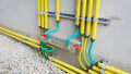
The grounding electrode is capable of conducting the electric current and connecting an electric system to the earth. The grounding electrode conductor bonds the grounded conductor to the grounding electrode system. Joining several independent grounding electrodes forms a grounding electrode system.

Image used courtesy of Pixabay
National Electrical Code Section 250.50
Section 250.50 deals with the grounding electrode system required at the service entrance.
This section requires bonding some metallic components present in the building served and other admitted electrodes to form the grounding electrode system. Sections 250.52(A)(1) to (7) describe these elements – the grounding electrodes.
If none of those grounding electrodes exist, one or more of the ones described in sections 250.52(A)(4) to (8) must be built and used.
Electrodes (A)(4) to (8) are easier to construct in a completed building missing electrodes (A)(1) to (7). This rationale is probably the basis for the exception to the rule, which allows not bonding the concrete-encased electrodes in existing buildings if this action may spoil the concrete.
The NEC ponders these elements when they are “present” at each building or structure. Previous editions of the NEC referred to these metallic items as “available” on the premises. Accordingly, bond the element if it is present, even though it is unavailable. This change has significant consequences, particularly in Section 250.50(A)(3), “Concrete-encased electrode,” as will be seen later.
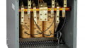
Section 250.30, and not Section 250.50, covers separately derived systems – a transformer secondary neutral, for example. See sections 250.30(A)(4) and 250.30(B)(2).
National Electrical Code Section 250.52
This section describes the systems and materials permitted and not permitted as grounding electrodes.
Section 250.52(A) Electrodes Permitted
Sections 250.52(A)(1) to (8) portray the electrodes permitted for grounding.
Bond the electrodes described in sections 250.52(A)(1) to (7). Install one or more electrodes as depicted in sections 250.52(A)(4) to (8) if none of the former exist.
250.52(A)(1) Metal Underground Water Pipe
Figure 1 shows the grounded conductor bond to a metal underground water pipe through the grounding electrode conductor.

Figure 1. Using a metal underground water pipe as a grounding electrode. Image used courtesy of Lorenzo Mari
Meet the following conditions for the water pipe to qualify as a grounding electrode
- Available on-site
- Built-in metal
- Underground and in direct contact with the earth for a minimum length of 3 m, including whichever metal well casing is bonded to the tube
- Electrically continuous–bonded around water meters and filters
Figure 2 shows a ground clamp for the water pipe.

Figure 2. Cast bronze ground clamp for a water pipe to tap conductor. Image used courtesy of Burndy
250.52(A)(2) Metal In-ground Support Structures
This electrode comprises one or more metal support structures in contact with the earth in a vertical direction for at least 3 m, with or without concrete lining. See Figure 3.
Examples of metal in-ground support structures are casings, pilings, and other structural metals.
It is permitted to bond only one support structure if several are available.

Figure 3. Structural member in contact with the earth. Image used courtesy of Lorenzo Mari
250.52(A)(3) Concrete-Encased Electrodes
A concrete-encased electrode enhances grounding in most any climatic and soil condition. This effective technique, named Ufer after Herbert G. Ufer, who developed it, takes advantage of the concrete foundations in buildings and structures.
Meet the following requirements for the construction to qualify as a concrete-encased electrode
- Use a minimum of 6 m length of electrically conductive rebar size ½” or higher. If multiple pieces are present, connect them with exothermic welding, steel tie wires, welding, or other suitable means
- Use a bare copper conductor size N° 4 AWG or higher as an option
- In either case, place the conductive material within at least 50 mm of concrete horizontally within the portion of the concrete foundation, footing contacting the earth, and vertical foundations or structural components reaching the ground
Section 250.68(C)(2) permits using the metal frame of the building as the grounding electrode conductor or as a conductor to interconnect other electrodes by securing the steel column with hold-down bolts connected to a concrete-encased electrode per Section 250.52(A)(3). See Figure 4.

Figure 4. Structural metal frame of a building connected to a concrete-encased electrode. Image used courtesy of Lorenzo Mari
For a structural metal frame of a building to qualify as a grounding electrode, it must contact the earth vertically for a minimum of 3 m, as required by Section 250.52(A)(2).
It is permitted to bond only one concrete-encased electrode if several are available.
When the building foundations are on layers of sand and plastic materials used as vapor barriers–mainly to avoid the effects of climate–the foundations are ineffective in contacting the earth.
Using the word present instead of available in Section 250.50 obliges the bonding of at least one foundation that qualifies as a concrete-encased electrode if it exists. Factor this criterion into the project schedule, as pouring the concrete may occur before making the electrical connection, and you’ll have to break the foundation, a cumbersome activity. Recall that the exception to Section 250.50 waives this rule in existing buildings if the action may damage the concrete.
Be careful when using the Ufer system, as rebar corrosion or large ground-fault currents may spoil the concrete. Corroded steel can double its original volume, and a fault current can generate enough heat to convert moisture to high-pressure steam, producing cracks in the concrete.
250.52(A)(4) Ground Ring
A ground ring shall comply with the following:
- Encircle the building
- Have direct contact with the earth
- Length not less than 6 m
- Made with a copper conductor of size not smaller than N° 2 AWG
- Section 250.53(F) requires a minimum depth of 750 mm
250.52(A)(5) Pipe and Rod Electrodes
The conditions for pipes and rods to qualify as grounding electrodes are
- 2.44 m (8’) minimum length
- Pipe and conduit not smaller than trade size 3/4”
- Steel pipe and conduit must be galvanized or otherwise metal-coated against corrosion
- Stainless steel, copper, or zinc-coated steel rods must be a minimum of 5/8” in diameter unless listed as grounding electrodes
Figure 5 shows copper-clad 5/8” x 8’ ground rods, and Figure 6 shows a ground rod clamp to connect the conductor.

Figure 5. Ground Rods 5/8''x8’. Image used courtesy of GOUNENGNAIL

Figure 6. Clamp for 1/2”- 5/8” grounding rods. Image used courtesy of GOUNENGNAIL
250.52(A)(6) Listed Electrodes
The NEC permits listed grounding electrodes. The listed rods may be less than 5/8” in diameter.
As an application example, Figure 7 shows UL Listed horizontal and vertical chemical rods–enhanced electrodes made of punched copper pipe filled with chemicals.

Figure 7. UL Listed chemical rods. Image used courtesy of Lightning Eliminators
250.52(A)(7) Plate Electrodes
The plate electrodes must
- Expose no less than 0.186 m² to the soil
- Plates exposing both sides to the ground require a minimum surface area of 0.093 m²
- Iron and steel plates have at least 6.4 mm (1/4”) thickness
- Nonferrous metal plates have at least 1.5 mm (0.06”) thickness
Figure 8 shows a steel ground plate 1/4” thick with a welded steel rod pigtail.

Figure 8. Steel ground plate. Image used courtesy of ERICO
250.52(A)(8) Other Metal Underground Systems
Recall Section 250.50 requiring one or more of the grounding electrodes described in sections 250.52(A)(4) to (8) if the ones in sections 250.52(A)(1) to (7) do not exist. Here, Section 250.52(A)(8) comes into play.
Section 250.50 does not include Section 250.52(A)(8) as mandatory – bonding these elements is voluntary.
Bonding to one of these electrodes would satisfy Section 250.50 when the electrodes in 250.52(A)(1) through (7) are missing.
Examples of this type of grounding electrode are
- Piping systems
- Underground metal tanks
- Underground metal well casings not bonded to a metal water pipe–when connected, Section 250.52(A)(1) includes the case
Figure 9 summarizes the rule in Section 250.50 by bonding four grounding electrodes present at the building, forming the grounding electrode system.

Figure 9. Grounding electrode system. Image used courtesy of Lorenzo Mari
Utilizing the listed devices will ensure good electrode performance. Listed devices are for use with copper unless marked “Cu and Al.”
Employing rods, pipes, and plates is typical when other electrodes are unavailable. This practice does not guarantee that the resistance to the ground will be sufficiently low; therefore, Section 250.53(A)(2) requires a supplemental electrode. The exception to this rule waves this requirement if the measured resistance to ground is 25 Ω or less.
Whatever the grounding electrode system’s final configuration, measuring the resistance to the ground after completing the construction is vital.
Section 250.52(B) Not Permitted for Grounding Electrodes
The following systems and materials do not qualify as grounding electrodes
- Metal underground gas piping. Follow Section 250.104(B) for bonding requirements.
The reasoning for this rule is that gas utility companies decline this practice, which also conflicts with standards in other industries.
- Aluminum structures
- The structural rebar in pools
Takeaways of Grounding Electrode Systems
- Bond all grounding electrodes in a building to form the grounding electrode system.
- Sections 250.52(A)(1) to (8) describe the grounding electrodes recognized by the NEC.
- Make and use one or more of the grounding electrodes described in sections 250.52(A)(4) to (8) if no other electrode is present.
- Bond meters and filters in water pipes to maintain electrical continuity.
- The Ufer system is suitable even in dry and sandy soils, but be careful in its application as corrosion and large ground-fault currents can fracture the concrete.
- Always measure the resistance to the ground after completing the work.