Facebook
 Google
 GitHub
 Linkedin
Defining Voltage Pulse Test Requirements for Insulation Endurance Assessment
Rapid progress in fast-switching devices presents new challenges that must be addressed by insulation material manufacturers and system integrators.
This article is published by EEPower as part of an exclusive digital content partnership with Bodo’s Power Systems.
Power electronics technology is continuously advancing, so requirements are always changing. In particular, the rapid progress in fast-switching devices presents new challenges that insulation material manufacturers and system integrators must address.
The insulation systems of rotating machines, transformers, cables, or bearings experience significantly higher stress due to steep dv/dt voltage pulses generated by inverters. This trend is further amplified by the increasing system voltage in many applications, as observed in electric vehicles (400 ➜ 800 V) and PV systems (1000 ➜ 1500 V). The application of steep inverter dv/dt slopes leads to increased stress compared to the traditional 50 Hz sinusoidal voltage due to:
- Reduced partial discharge inception voltage (PDIV) and increased partial discharge activity.
- Inhomogeneous voltage distribution within the windings.
- Polarization effects and dielectric heating due to displacement currents.
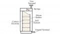
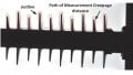
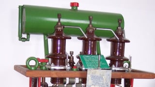
Figure 1a illustrates a twisted wire test specimen undergoing stress during inverter operation. Strong corona discharge activity is visible to the naked eye. Figure 1b shows an example of a destroyed motor caused by failed insulation. In Figure 1c, conventional enamel wire insulation, also configured as a twisted pair, underwent testing with pulsed voltages, revealing distinct indications of partial discharge erosion.
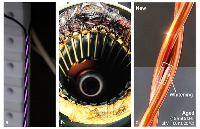
Figure 1a. test specimens with strong corona discharge; Figure 1b. motor example; Figure 1c. twisted pair wire after endurance testing (tested at Hannover lab). Image used courtesy of Bodo’s Power Systems [PDF]
Under these challenging operating conditions, precise knowledge of the aging process and the ability to estimate the remaining lifespan of the insulation system are crucial.
Saxogy and Hannover University of Applied Sciences have developed a test bench that realistically simulates the stresses of inverter operation and can be used for accelerated insulation endurance assessment. The corresponding project, “ISODyn,” was supported by German ZIM research funding.
Requirements for Testing
There is no unified international standard for winding wire endurance testing under high-frequency voltage impulses, so we refer to the existing Chinese standard GB/T 4074.21-2018 and incorporate feedback from manufacturers to derive the following requirements (Figure 2) that the dv/dt pulse generator must meet.
- Voltage waveform: Bipolar square wave
- Peak voltage: 1.5 kV (should be modular extendable)
- Rise time tr > 25 ns (10-90%) – adjustable
- Max. voltage slope dv/dt: 60 kV/µs
- Pulse frequency: 20 kHz
- Test temperature >180 °C
- Voltage overshoot (1-Up/Ua) < 2%
- Grounding of the device under test
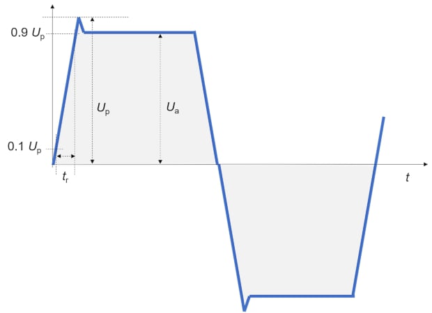
Figure 2. Specification of the voltage waveform over one period. Image used courtesy of Bodo’s Power Systems [PDF]
The motor winding breakdown due to insulation failure occurs when the insulation degrades under steep dv/dt voltage pulses. This degradation leads to arcing, reducing the insulation resistance and resulting in a breakdown. Reliable detection is necessary to prevent damage to the test bench and accurately define the resulting lifetime.
Factors Influencing Insulation Lifetime
Endurance tests carry out various measurements. The results were subjected to statistical analysis. The test samples consist of twisted pair copper wires specified to the IEC 60851 standard.
The influence of the pulse frequency fp on the resulting electric lifetime of conventional copper wire enamels without additives was investigated (Figure 3). On average, the samples failed after about 4 minutes (for 11 kHz) to about 55 minutes (for 1 kHz). The electric lifetime decreases almost linearly with increasing frequency fp.
Figure 3. Probability plot of the electric lifetime depending on switching frequency. Image used courtesy of Bodo’s Power Systems [PDF]
Additionally, the effects of slew rate, temperature, and insulation material on the resulting lifetime were investigated, examining combinations of rise time (tr) and oven temperatures (Figure 4).
- Variations in rise time had a noticeable impact on lifetime
- Increasing the temperature reduces the electric lifespan
The choice of insulation material and its structural composition significantly influenced the overall lifetime.
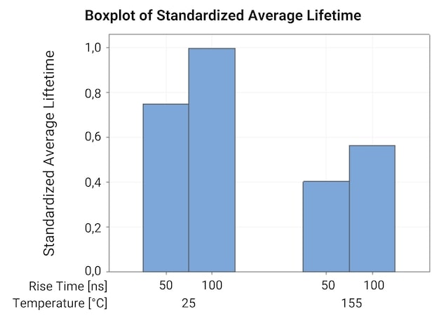
Figure 4. Impact of rise time and temperature on conventional copper wire enamel lifetime. Image used courtesy of Bodo’s Power Systems [PDF]
Unique Modular dv/dt Pulse Generator Test Bench for Lifetime Testing
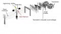
Saxogy and Hannover University of Applied Sciences jointly developed a modular high-voltage pulse generator, as shown in Figure 5.
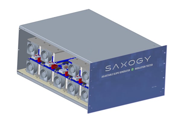
Figure 5. Sketch of the power unit of the dv/dt pulse generator. Image used courtesy of Bodo’s Power Systems [PDF]
This generator uses state-of-the-art SiC MOSFET technology. It is designed to be adaptable, allowing expansion to fulfill the specific test requirements for lifetime testing and upcoming insulation testing standards.
The concept is scalable and can be expanded to meet specific application needs. The bipolar voltage waveform is adjustable across a broad voltage range, from 0.4 kVpp to 12 kVpp, depending on the configuration, and the generator can achieve voltage slopes up to 200 kV/µs.
Adjustable Load Settings
A precise gate driver circuit has been developed to ensure the SiC inverter’s overshoot remains below 2%.
Furthermore, an almost linear voltage gradient was achieved during the switching time, ensuring consistent stress in every rising and falling edge. To adjust the stress level, 16 steps are required to fine-tune the voltage slope based on the requirements of the individual insulation testing standard. To vary the test time for accelerated endurance tests, the generator’s square wave frequency can be set between 2 kHz and 20 kHz.
In addition to the electrical key figures for insulation testing, the development focused on two essential requirements for an insulation endurance test bench:
- The generator must never exceed its insulation limits and cause stress to itself
- Most insulation tests end with an insulation breakdown, which, from the generator’s point of view, represents a low-impedance short circuit. This short-circuit current must be detected and handled within microseconds, and this process is repeated beyond the device’s lifetime.
Research and Development in Accelerated Insulation Endurance Testing
The collaborative effort has resulted in developing an advanced modular dv/dt pulse generator. This innovative test bench represents a significant leap in accelerated insulation endurance testing. It offers a valuable tool for validating existing and developing new insulation systems, contributing to enhancing future power electronic systems.
This article originally appeared in Bodo’s Power Systems [PDF] magazine and was co-authored by Benjamin Sahan and Konrad Domes of Saxogy Power Electronics GmbH.