Facebook
 Google
 GitHub
 Linkedin
High-Voltage Testing and Insulation Coordination—Part 4
In this article, learn methods for mitigating lightning- and switching-induced overvoltages in high-voltage networks through surge arresters, shielding, and insulation coordination.
The article discusses methods for mitigating lightning- and switching-induced overvoltages in high-voltage networks, focusing on the role of metal-oxide surge arresters, shielding techniques, and insulation coordination. It also compares protection considerations in gas-insulated (GIS) and air-insulated (AIS) switchgear systems.
Effective mitigation of lightning- and switching-induced overvoltages in high-voltage networks hinges on two complementary strategies: (1) installation of surge arresters, primarily based on metal-oxide varistor (MOV) technology, and (2) field shielding techniques, including ground wires, optimized shielding angles, and tower grounding. These methods are designed to ensure that insulation stress remains within withstand limits under transient conditions, and that surge energy is safely dissipated without initiating flashover or equipment damage.
Metal-Oxide Varistor (MOV) Arresters
MOV arresters, also referred to as gapless metal-oxide surge arresters, are non-linear voltage-dependent resistive devices designed to divert surge currents to ground during transient overvoltage events. Their voltage-current characteristic is typically represented by the equation:
$$I = kV^n$$
where:
- I is the current through the arrester
- V is the voltage across the arrester
- n is the non-linearity coefficient (typically 20–50)
- k is a material constant dependent on ZnO doping
Selection criteria for MOV arresters include:
- Continuous Operating Voltage (Uc): Should exceed the maximum phase-to-ground voltage under normal and temporary overvoltage (TOV) conditions.
- Discharge voltage: Peak voltage during a specified surge current (such as 10 kA lightning impulse). This value must be lower than the insulation withstand level (typically BIL minus coordination margin).
- Energy absorption capability: Especially critical for switching surges and long-duration temporary overvoltages. Arresters at EHV substations may be rated for multiple joules per kV of MCOV (Maximum Continuous Operating Voltage).
Placement guidelines:
- Arresters are installed at transformer terminals, cable terminations, and line entrances to protect sensitive equipment.
- For overhead lines, they are often placed at the first tower near a substation to intercept incoming surges.
- In GIS and compact switchgear, MOV units are embedded within or adjacent to bushings.
To avoid arrester overload, coordination with expected discharge energy is critical. For example, in 400 kV systems with long transmission lines, switching surges may deposit significant energy into arresters. IEEE Std C62.11 provides standardized duty cycles for evaluating arrester performance under multiple surge conditions.
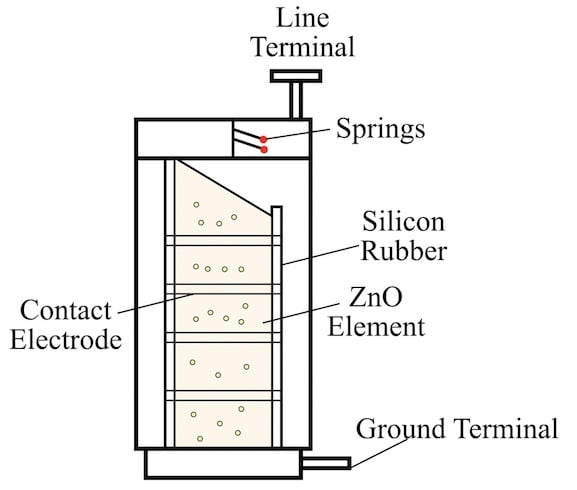
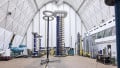
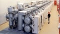
Figure 1. MOV arrester. Image used courtesy of ResearchGate
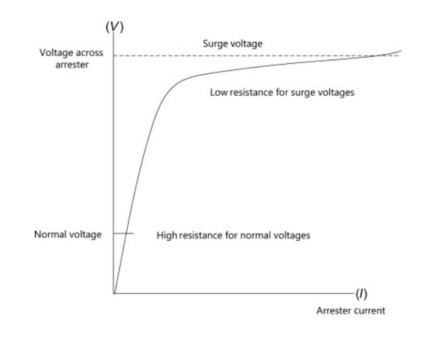
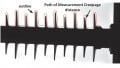
Figure 2. Voltage-current characteristics of ZnO surge arrester. Image used courtesy of ScienceDirect.
Discharge Voltage vs Residual Energy Coordination
MOV arresters operate by clamping the surge voltage and conducting the surge current to ground. This process involves energy dissipation through the arrester body. The discharge voltage is the maximum voltage across the arrester terminals during a specified surge waveform, and must satisfy:
$$V_{dis} < V_{withstand} - \Delta V_{margin}$$
Where:
- Vdis is the arrester’s discharge voltage
- Vwithstand is the equipment’s impulse withstand level (for example, BIL)
- ΔVmargin is the coordination margin (usually 15–25%)
The residual energy absorbed is a function of the current waveform and duration. Arrester designs vary from distribution class (kJ-level energy) to station class (MJ-level capacity), with special considerations for UHV applications, where energy dissipation per surge may exceed 10–15 kJ.
Modern station-class arresters are designed with grading rings and multiple ZnO blocks to ensure uniform voltage distribution and minimal heating under prolonged discharge conditions. Their energy rating is validated through a multi-shot test (per IEEE C62.11), where the arrester is subjected to multiple impulses with specified energy content and cooling intervals.
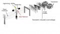
Shielding Angles and Tower-Top Grounding
In transmission systems, field shielding through overhead ground wires (shield wires) is used to intercept direct lightning strokes before they contact phase conductors. The effectiveness of shielding is evaluated via shielding angle (θ) and protection zone geometry.
Shielding Angle
The shielding angle θ is the angle formed between the vertical line from the phase conductor and the line connecting the conductor to the shield wire:
$$\tan (\theta) = \frac{H_g - H_p}{D}$$
Where:
- Hg is the height of the ground wire
- Hp is the height of the phase conductor
- D is the horizontal distance between them
Typical design values:
- 20°–30° for EHV lines
- ≤20° for UHV systems to minimize the probability of shielding failure
The selection must balance protection against shielding failure flashovers and tower construction costs. For compact transmission towers or multi-circuit designs, two or more shield wires may be needed to cover all phases effectively.
Tower Footing Resistance and Surge Impedance
The efficacy of shielding is also dependent on tower footing resistance, which must be minimized (typically ≤10 Ω in high-risk areas) to prevent excessive voltage rise during surge current dissipation. Elevated footing resistance can result in backflashover, where the ground potential at the tower exceeds the line-to-ground voltage, causing the surge to jump back to a phase conductor.
Surge impedance loading (SIL) plays an indirect role in surge behavior. It defines the natural power-carrying capability of a line:
$$\text{SIL} = \frac{V^2}{Z_c}$$
Where Zc is the line surge impedance (typically 300–400 Ω). Lines with higher SIL (in other words, lower impedance) generally have faster wavefront propagation and may be more susceptible to reflection-induced overvoltages if arresters are not properly coordinated.
Coordination with Insulation
Effective surge protection in high-voltage systems hinges not only on the individual performance of arresters but on how well they are coordinated with the insulation levels of the protected equipment. Insulation coordination refers to the design and selection process by which protective devices (especially surge arresters) are specified such that the equipment insulation is not overstressed under overvoltage conditions.
This coordination must consider both transient and temporary overvoltages (TOV), the non-linear dynamic behavior of arresters, and the characteristics of the insulation system (such as gas, air, oil, or solid dielectrics).
Protective Margins: Withstand Level vs Arrester Discharge Voltage
The primary objective of insulation coordination is to ensure that the arrester discharge voltage remains safely below the insulation withstand level of the protected equipment. This margin is commonly referred to as the protective margin or coordination margin and is quantified as:
$$\text{Protective Margin (%)} = \big( \frac{U_{withstand} - U_{res}}{U_{res}} \big) \times 100 $$
Where:
- Uwithstand is the equipment’s impulse withstand level (e.g., BIL)
- Ures is the arrester residual (discharge) voltage under the relevant surge condition (such as 8/20 μs lightning, 30/60 μs switching)
Per IEEE C62.22, typical required protective margins are:
- 15%–25% for lightning impulses
- 20%–30% for switching impulses
This margin ensures that even under worst-case conditions—including arrester aging, voltage drop along leads, and transient overshoots—the protected insulation is not overstressed. In GIS, where the breakdown characteristics are steep and less tolerant than in AIS, higher protective margins are typically enforced (up to 25–30%).
To achieve such margins, engineers must minimize the lead length and inductance between arrester and protected equipment, particularly in EHV and UHV systems, where steep fronted surges can cause dangerous overshoots due to inductive drops:
$$V_L = L \cdot \frac{di}{dt}$$
Even a few microhenries of stray inductance (such as 1 μH at 10 kA/μs) can produce transient overvoltages of 10 kV, which must be accounted for in arrester location and connection design.
TOV Capability Curves and Temporary Overvoltage Coordination
Apart from fast-acting surges, insulation systems must also withstand temporary overvoltages (TOV) arising from fault recovery, resonance phenomena, or load rejection. Surge arresters are not only surge clamping devices but also must withstand elevated voltages over time without thermal runaway.
This is characterized using TOV capability curves, which define the time-duration withstand limits of the arrester under elevated power frequency overvoltages. A typical TOV curve plots per-unit voltage vs duration, often for a predefined reference temperature (such as 60°C). For example, a station-class arrester rated at 336 kV may withstand:
- 1.5 p.u. for 1 second
- 1.3 p.u. for 10 seconds
- 1.15 p.u. continuously
These curves are essential for coordinating with the system grounding configuration. In ungrounded or resonant-grounded systems, TOVs can persist for hundreds of milliseconds following SLG faults. Arrester selection must thus ensure TOV withstand exceeds worst-case expected durations based on system protection clearing times.
In practice, this coordination is validated using the equation:
$$V_{TOV} \le U_c \cdot k_t$$
where:
- VTOV is the expected TOV peak
- Uc is the arrester’s continuous operating voltage
- kt is the permissible TOV overvoltage factor (from manufacturer-provided TOV curve)
Failure to satisfy TOV criteria may lead to arrester overheating, degradation, or explosive failure—especially in systems with slow fault clearing or ferroresonance.
Figure 3. Temporary overvoltages (TOV) capability curves. Image used courtesy of TestGuy.net.
Protection Schemes in GIS vs AIS
Insulation coordination differs fundamentally between gas-insulated switchgear (GIS) and air-insulated switchgear (AIS) due to the dielectric properties and geometric constraints of the insulation medium.
Gas-Insulated Switchgear (GIS)
In GIS, the insulation is typically SF₆ or SF₆ mixtures, offering high dielectric strength and fast breakdown response. However, the system is extremely compact, and the breakdown voltage characteristics are sharp and less tolerant to overshoots. As a result:
- BIL and BSL (Basic Switching Level) ratings in GIS are often lower than AIS for the same system voltage.
- Shielding electrodes, grading capacitors, and capacitive dividers are used to ensure uniform voltage distribution.
- Arrester installation in GIS is usually integral to the equipment design, and the lead length between the arrester and protected equipment is minimized to a few centimeters.
Due to the steep wavefronts in GIS, coordination is waveform-sensitive: a surge with a front time <0.5 μs may cause flashover even if its peak value is below the rated BIL, due to energy concentration. Thus, front-of-wave coordination becomes essential in GIS, and surge arresters must be selected for both front-of-wave and standard 1.2/50 μs impulses.
Air-Insulated Switchgear (AIS)
In AIS, clearances are significantly larger and less constrained by enclosure geometry. Air has a longer breakdown time lag, making AIS somewhat more tolerant to fast-rising surges. However:
- Environmental factors (humidity, pollution, altitude) heavily influence insulation behavior.
- Flashover occurs externally, and thus can involve longer arcs and external damage.
- Lead lengths to arresters are often longer, increasing inductive overshoot risks unless mitigated via interconnection design or supplementary grading devices.
Arrester coordination in AIS often involves both station-class MOV units and supplementary shielding, especially in EHV substations (>400 kV), where switching surges drive the insulation design.
| Parameter | GIS | AIS |
| Insulation Medium | SF₆ or gas mixtures | Air |
| Breakdown Response | Fast, steep-front sensitive | Slower, more tolerant |
| Arrester Location | Integrated, minimal leads | External, longer leads |
| BIL Level (for same kV) | Lower (due to compactness) | Higher (due to clearance) |
| Surge Propagation | High-frequency dominated | Moderate-frequency |
| Front-of-wave Coordination | Required | Usually not required |
| Shielding Techniques | Internal grading electrodes | Overhead shield wires |
Table 1. GIS vs AIS Coordination Considerations
Key Takeaways
Managing lightning- and switching-induced overvoltages through surge arresters, shielding, and insulation coordination plays a vital role in maintaining secure and resilient high-voltage networks. By properly selecting and coordinating protective devices with system insulation, utilities can minimize equipment failures, reduce downtime, and enhance the stability of power transmission. These practices are especially critical in modern EHV and UHV applications, where the consequences of insulation breakdown are both technically and economically significant.