Facebook
 Google
 GitHub
 Linkedin
High-Voltage Testing and Insulation Coordination—Part 1
In this article, we explore high-voltage insulation coordination, focusing on the nature of overvoltages, standardized impulse and withstand voltage testing methods, and the role of standards for reliability.
High-voltage insulation plays a central role in ensuring the operational security and long-term reliability of modern power systems. From overhead transmission lines to power transformers and GIS substations, insulation systems are designed to withstand not only continuous service voltages but also transient overvoltages arising from both external and internal sources.
A failure of insulation—whether in the air, solid dielectrics, or oil-paper systems—can lead to arc flashovers, equipment damage, service interruptions, and in some cases, cascading grid failures. As system voltages continue to rise to meet growing power transfer demands, insulation performance becomes increasingly critical.
The insulation of a system must be robust enough to survive various stress scenarios, including dielectric breakdown, partial discharges, and long-term aging mechanisms. These stressors are not only dependent on the voltage magnitude but also on wave shape, duration, polarity, and rate of rise (dv/dt). As a result, insulation systems are always specified and validated against standardized voltage waveforms that simulate real-world surge conditions.
Nature and Sources of Overvoltages
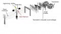
Overvoltages in power systems originate from a range of phenomena. The most prominent external cause is lightning, which can introduce high-amplitude, steep-front surges into transmission lines, typically propagating as traveling waves. These surges are particularly dangerous due to their short rise time and high peak voltage, often exceeding several hundred kilovolts.
Internally, the dominant cause of overvoltages is high-speed switching of inductive or capacitive elements such as circuit breakers, power transformers, shunt reactors, and capacitor banks. Such operations may generate slower-front but still significant overvoltages with oscillatory components and extended duration.
Other contributors include temporary overvoltages (TOV), which can arise from load rejection, resonance conditions, ferroresonance in power transformers, or long line energization. While their amplitudes are generally lower than lightning or switching surges, TOVs can persist for several cycles or even seconds, making them especially hazardous for insulation systems designed for transient events.
The insulation system must therefore withstand three broad categories of overvoltage:
- Lightning overvoltages (fast-front, high amplitude)
- Switching overvoltages (slow-front, moderate amplitude)
- Temporary overvoltages (low frequency, sustained duration)
These classifications inform the insulation coordination process, which involves careful selection of dielectric withstand levels and protective device settings.
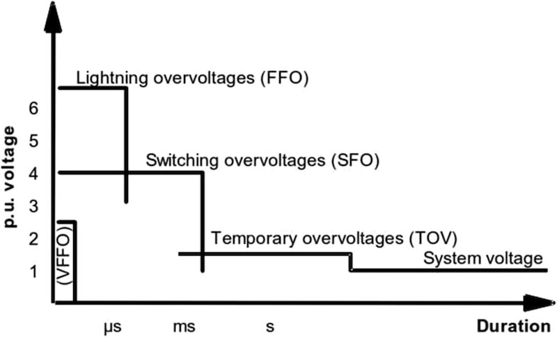
Characteristics of all types of overvoltages. Image used courtesy of ResearchGate.
Insulation Coordination: Matching Strength with Protection
Insulation coordination is the deliberate engineering process of aligning the dielectric strength of equipment with the expected severity of overvoltages and the operation characteristics of protective devices, such as surge arresters. It ensures that:
- The equipment insulation is neither underutilized nor excessively overdesigned.
- Protective devices operate before the system insulation is overstressed.
This coordination is governed by international standards such as IEC 60071-1 and IEEE Std 1313.1, which define standard insulation levels, statistical withstand probabilities, and protective margins. Insulation coordination does not aim to eliminate all overvoltages; instead, it ensures that the probability of insulation failure remains within acceptable limits based on system voltage, insulation type, and protection schemes.
For instance, a power transformer rated at 400 kV might have a Basic Insulation Level (BIL) of 1425 kV (lightning impulse) and a Switching Impulse Withstand Level (SIL) of 1050 kV. These values are not arbitrary but based on decades of high-voltage testing, statistical insulation breakdown data, and real-world surge profiles.
Engineering Relevance and Applications
Effective insulation coordination directly influences the design, testing, and operation of all major high-voltage equipment:
- Transformers must have winding insulation and bushings designed to withstand both lightning and switching impulses.
- Circuit breakers must not only interrupt fault currents but must also handle transient recovery voltages (TRV) and prevent internal breakdowns.
- Surge arresters (such as metal oxide varistors) are tuned to clamp overvoltages just below the withstand threshold of protected equipment.
- Overhead lines and cables must be evaluated for their surge impedance, propagation characteristics, and exposure to lightning strokes.
Furthermore, insulation coordination plays a critical role in grid stability. A poorly coordinated system may experience insulation failures even under normal switching operations, leading to misoperations, forced outages, and blackouts. From the perspective of system planners and protection engineers, insulation coordination ensures compliance with design codes while optimizing system performance and minimizing equipment cost.
Impulse and Withstand Voltage Testing Standards
High-voltage equipment must be validated under carefully controlled laboratory conditions to ensure that its insulation can endure operational and transient stresses. The primary standards governing high-voltage testing procedures are IEC 60060 (for high-voltage test techniques) and IEEE Std 4, which provide nearly parallel methodologies for testing apparatus insulation using impulse and power-frequency voltages.
These standards define the procedures, measurement techniques, test waveforms, and acceptance criteria for evaluating insulation strength in a reproducible and internationally accepted manner.
The core objective of impulse testing is to simulate realistic overvoltage conditions—particularly those due to lightning and switching events—using standardized waveform profiles. The most common test waveforms are:
- Lightning Impulse (LI): Characterized by a nominal wave shape of 1.2/50 μs (1.2 μs front time, 50 μs time to half-value), this waveform emulates a direct or indirect lightning strike’s steep-front surge. The waveform is defined by IEC 60060-1, and its parameters are tightly regulated to ensure consistency.
- Switching Impulse (SI): With a significantly slower front time, typically 250/2500 μs, this waveform represents internal overvoltages due to switching of high-voltage equipment, such as circuit breakers or load rejection events. In HVDC and EHV applications, switching impulses can be more destructive than lightning impulses due to their longer energy duration.
- Power-Frequency Withstand: This test applies a continuous 50 Hz or 60 Hz sinusoidal voltage for 1 minute to simulate sustained overvoltages or temporary faults. It is mainly used to assess insulation performance under steady-state but elevated conditions.
These tests are typically conducted in high-voltage laboratories equipped with impulse voltage generators, capable of producing impulses in the range of several megavolts. A standard generator may consist of multiple stages of capacitors and spark gaps arranged in a Marx configuration to sequentially add voltages and create the required waveform.
Voltage dividers, typically capacitive or resistive, are employed to scale down the high voltage for accurate measurement. The waveform is captured using digital oscillography, with peak voltages, front time, and tail time analyzed for compliance with standard wave shapes. The measurement setup must be properly shielded and grounded to eliminate noise and corona discharge artifacts that can corrupt the impulse waveform.
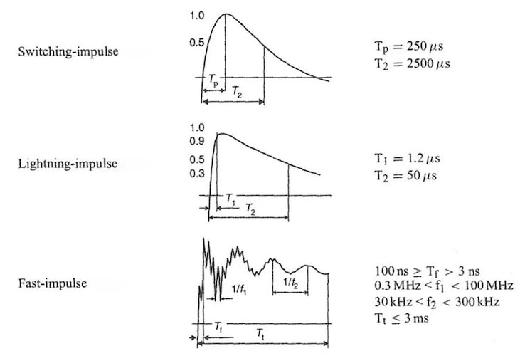
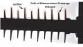
Common waveforms for testing of insulation systems. Image used courtesy of MB Drive Services.
Withstand Criteria and Test Classification
The outcome of high-voltage testing is generally binary—either the insulation “withstands” the applied voltage or “fails” through flashover or puncture. To define this more precisely:
- Withstand means the equipment survives the test voltage without any disruptive discharge or permanent damage to its insulation system.
- Flashover is the discharge path across the air or surface insulation, not through the dielectric material. It is not always destructive, but it is considered a test failure if it violates design expectations.
- Breakdown or puncture refers to irreversible insulation failure, typically within solid or liquid insulation media.
Testing is conducted under standard atmospheric conditions defined by temperature (20°C), pressure (101.3 kPa), and relative humidity (11 g/m³). Since atmospheric conditions affect air density and hence dielectric strength, both IEC and IEEE standards require correction factors when tests are performed under non-standard conditions.
Air Density Correction Factor
$$K_1 = \large(\frac{p}{p_0}\cdot\frac{T_0}{T} \large)^m$$
Where
- K1 Air Density correction factor
- p Atmospheric pressure at site (kPa)
- p0 Standard pressure = 101.3 kPa
- T Absolute temperature at site (K = °C + 273.15)
- T0 Standard temperature = 293 K (20 °C)
- m Exponent depending on voltage type (typically 1 for Lightning impulse, Switching impulse, Power frequency)
Altitude Correction Factor
$$K_a = e^{\frac{m(h-1000)}{8150}} \text{ for } h > 1000 \text{ m}$$
Where
- h Altitude above sea level in meters
- m Exponent depending on voltage type (typically 1 for Lightning impulse, Switching impulse, Power frequency)
These corrections ensure consistent test severity across different laboratories and environmental setups.
Depending on the test objective, several impulse test variants may be used:
- Full-Wave Test: A standard 1.2/50 μs waveform is applied. The equipment must withstand a predefined number of applications (commonly 3 to 5 shots).
- Chopped-Wave Test: The impulse is intentionally chopped on the tail or front using an external spark gap. This simulates a nearby flashover or arrester operation and imposes a steeper dv/dt on the insulation.
- Front-of-Wave Test: This evaluates insulation response to the extremely steep rise of a lightning stroke’s front (~0.1–0.5 μs). These are rare but critical in GIS applications or transformer bushings near exposed terminals.
Tests are classified as dry or wet, with wet testing performed under simulated rain conditions (typically 1–3 mm/min using deionized water). Wet tests are essential for outdoor equipment to account for surface contamination and water-film conduction paths. Standards define minimum withstand voltages for both dry and wet conditions, and equipment must pass both to be certified for outdoor high-voltage operation.
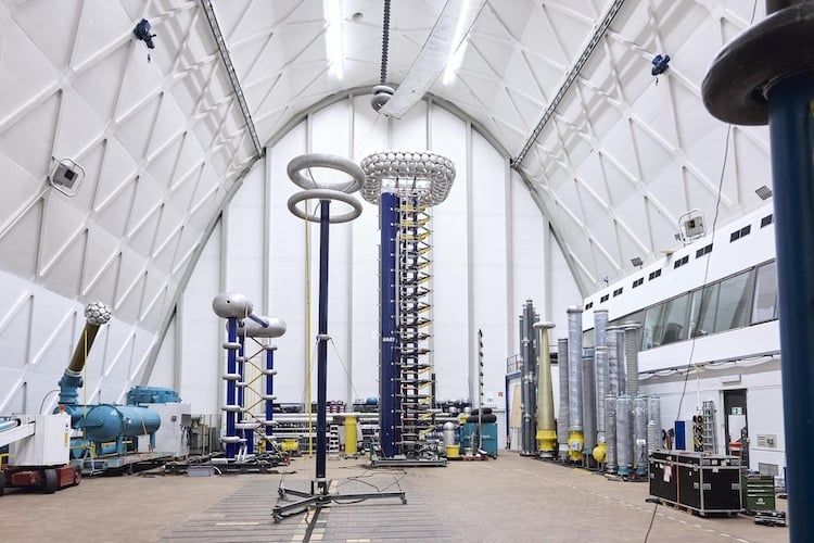
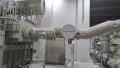
High-voltage testing environment. Image used courtesy of Siemens Energy.
Key Takeaways
Impulse and withstand voltage testing are foundational elements of high-voltage engineering practice. The waveforms, pass/fail criteria, and testing protocols established by IEC and IEEE standards ensure that all equipment entering service has a verified margin of safety against expected overvoltage events. These standardized procedures form the empirical basis for insulation coordination and directly influence the selection of insulation materials, clearances, and surge protection schemes.