Facebook
 Google
 GitHub
 Linkedin
Choosing the Correct Current Value to Design Motor Circuits
Learn about using the correct current values when designing and calculating motor circuits.
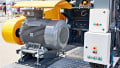
Many industrial and domestic processes require converting energy from a readily available form to one more appropriate for utilization. The electric motor is one common type of machine employed for such energy conversion. Follow NEC’s Article 430 rules to install safe electric motor circuits.

Image used courtesy of ABB
No other form of motive power can parallel electric motors' dependability, versatility, and economy of operation. A substantial percentage of industrial and domestic applications utilize motors, significantly impacting our daily lives.
Part I General: National Electrical Code Section 430.1 Scope
Article 430 comprises the following topics:
- Electric motors
- Branch-circuit and feeder conductors (Part II)
- Motor and branch-circuit overload protection (Part III)
- Branch-circuit short-circuit and ground-fault protection (Part IV)
- Feeder short-circuit and ground-fault protection (Part V)
- Control circuits (Part VI)
- Controllers (Part VII)
- Control centers (Part VIII).
- Disconnecting means (Part IX)
- Adjustable-speed drive systems (Part X)
- Over 1kV, nominal (Part XI)
- Protection of live parts (Part XII)
- Grounding (Part XIII)
- Tables (Part XIV)
A motor branch circuit includes the elements shown in Figure 1.

Figure 1. Essential components of a motor branch circuit. Image used courtesy of Lorenzo Mari
Wound-rotor motors use secondary resistors, controllers, and conductors.
Although the NEC does not rule the calculation sequence when specifying the components of the motor branch circuit, the following order for the six essential parts has proven appropriate:
1. Branch-circuit conductors—select the conductors
2. Branch-circuit short-circuit and ground-fault protection—protect the circuit
3. Controller—must be suitable for the load and supply system
4. Overload protection—open the circuit under overload conditions
5. Disconnecting means—providing a way to disconnect the motor and controller from the power source
6. Remote control circuit—providing manual or automatic operation of the controller
In particular circumstances, the NEC permits a single element to perform several functions. Examples are:
- A circuit breaker or set of fuses providing short-circuit and overload protection
- One switch works as a disconnecting means and the controller
National Electrical Code Section 430.2 Reconditioned Motors
Old motors can often be repaired or rebuilt at a reasonable price to keep them in service. When old motors have suitable characteristics for an application, rebuilding them can achieve considerable savings relative to the cost of a new motor. It is usually more economical to rewind large integral-horsepower motors that have “burned out” than to replace them with new ones.
The cost of rewinding small motors is usually more significant than the price of new ones. Consequently, a typical practice is replacing small motors.
The NEC permits employing reconditioned motors if the reconditioning process follows the manufacturer’s instructions or nationally recognized standards.
Reconditioned motors must be listed as reconditioned in hazardous (classified) locations.
The Informational Note directs to the standard ANSI/EASA AR100-2020 “Recommended Practice for the Repair of Rotating Electrical Apparatus.”
National Electrical Code Section 430.4 Part-Winding Motors
“Part-winding” starting is a method to reduce the starting current. This approach arranges the stator winding in a way that allows energizing one part of it first and the remainder of the winding in a second step. This sequential process requires the use of adequate control devices.
- Protect each half of the motor winding individually per sections 430.32 “Continuous-Duty Motors” and 430.37 “Devices Other than Fuses” with a trip current of one-half that specified—when using separate overload devices with standard part-winding start induction motors.
Figure 2 shows a squirrel cage induction motor (dual-voltage motor) with 220/440 V partial windings for use with a 220 V supply.
The starting process uses only one of the star-connected sections. The two switches shown simulate the type of starter employed on this type of motor—it comprises two magnetic contactors, each supplying one winding, rated for half the motor horsepower.
The resistance and reactance during starting are twice what they would be when connecting both windings in parallel, reducing the starting current by 35% and the starting torque by approximately 55%.
Due to the reduction in starting torque, the recommendation is to apply this method under light or no-load conditions, such as fans, blowers, or bench drills.
The second winding is connected in parallel when the motor reaches a specified speed.

Figure 2. Part-winding start induction motor. Image used courtesy of Lorenzo Mari
National Electrical Code Section 430.6 Conductor Ampacity and Motor Rating Determination
Size the conductors supplying the equipment covered by Article 430 using:
- Ampacity tables in Section 310.15
- Calculations per Section 310.14(B) “Engineering supervision”
- Section 400.5 “Ampacities for flexible cords and flexible cables”
Determine the conductor ampacity and motor ratings per sections 430.6(A) through (D).
Section 430.6(A) General Motor Applications
- Determine the current ratings based on sections 430.6(A)(1) and (2)
430.6(A)(1) Table Values
When dealing with motors other than low speed, high torque, or multispeed, employ tables 430.247, 430.248, 430.249, and 430.250 to choose the following:
- Conductor ampacities
- Switches’ current ratings
- Current ratings of branch-circuit short-circuit and ground-fault protection
Do not use the current rating marked on the motor nameplate.
Enter the tables with the motor horsepower and voltage ratings.
The advantage of using tables is keeping the motor circuit components when replacing a motor with another the same size, with a different current rating marked on the nameplate.
- Assume the horsepower rating of a motor marked in amperes as shown in Tables 430.247 through 430.250, interpolating when needed.
Example 1: Find the current to compute the size of the branch circuit conductor of a 440-V, 3-phase, 10-hp, squirrel-cage motor.
Answer: Enter Table 430.250 with 10 hp and read 14 A in the 460-V column.
Example 2: Find the full-load current of a 115-V, 1-phase, 2-hp motor connected to a 120-V power supply.
Answer: Enter Table 430.248 with 2 hp and read 24 A in the 115-V column.
Example 3: Find the full-load current of a 230-V, 3-phase, 5-hp motor connected to a 240-V power supply.
Answer: Enter Table 430.250 with 5 hp and read 15.2 A in the 230-V column.
The full-load current used in calculations for a sealed (hermetic-type) compressor motor is the nameplate value, not a table figure.
Example 4: Find the current to calculate the size of the branch circuit conductor of a sealed compressor motor whose nameplate shows a full-load current of 10 A.
Answer: Do not enter any table. Use the nameplate current = 10 A.
Exception N° 1: Follow Section 430.22(B), “Multispeed Motors” and Section 430. 52, ”Rating or Setting for Individual Motor Circuit“ for multispeed motors.
Exception N° 2: Use the motor full-load current marked on the nameplate of motor-operated appliances using:
- A shaded-pole or permanent-split capacitor-type fan
- A blower motor marked with the motor type and the marking on the equipment nameplate is not less than the current marked on the fan or blower motor nameplate to determine:
- Ampacity of the branch circuit conductor
- Current ratings of:
◦ Disconnecting means
◦ Motor controller
◦ Short-circuit and ground-fault protective devices
◦ Separate overload protective devices
Exception N° 3: Employ the motor full-load current marked on the nameplate of a motor-operated appliance that is marked with motor horsepower and full-load current to determine:
- Ampacity of the branch circuit conductor
- Current ratings of
◦ Disconnecting means
◦ Motor controller
◦ Short-circuit and ground-fault protective devices
◦ Separate overload protective devices
Example 5: The nameplate of a 115-V garage door opener shows a full-load current of 6 A. The device’s packaging displays a power of 1 hp. Find the current to compute the size of the branch circuit conductor.
Answer: Enter Table 430.248 with 1 hp and read a full-load current of 16 A.
16 A > 6 A
But Exception N° 3 requires using the full-load current marked on the nameplate.
Then, use a full-load current of 6 A.
430.6(A)(2) Nameplate Values
Use the current ratings marked on the motor nameplate to determine the following:
- Separate motor overload protection
- For low-speed, high-torque motors, canned pumps, and multispeed motors:
◦ Conductor ampacities
◦ Switches’ current ratings
◦ Current ratings of branch-circuit short-circuit and ground-fault protection
- Conductor sizing of large motors that exceed the values in Tables of Part XIV
Always use the nameplate full-load current when calculating overloads.
Section 430.6(B) Torque Motors
A torque motor develops high torque at a relatively low speed.
Use the locked-rotor current marked on the nameplate to determine:
- The ampacity of the branch-circuit conductors covered in Section 430.22, “Single Motor,” and Section 430.24, “Several Motors or a Motor and Other Loads”
- Current rating of the motor overload protection
- Current rating of branch-circuit short-circuit and ground-fault protection per Section 430.52(B)—must be capable of carrying the motor starting current
The motor’s locked-rotor current is the rated nameplate current. Protect the conductors and equipment of the branch circuit for a torque motor at the nameplate rating by selecting a fuse or circuit breaker per Section 240.4(G), “Overcurrent Protection for Specific Conductor Applications.” Also, use this current value for the conductor ampacity and the setting or rating of the overload protective device.
Section 430.6(C) AC Adjustable Voltage Motors
This section applies to motors used in alternating-current, adjustable voltage, and variable torque drive systems.
- Use the maximum operating current marked on the motor nameplate, the control nameplate, or both to determine the ampacity of conductors, current ratings of switches, branch-circuit short-circuit and ground-fault protection, etc.
- Determine the current rating based on 150% of the values in tables 430.249 and 430.250 if the maximum operating current does not appear on the nameplate.
Section 430.6(D) Valve Actuator Motor Assemblies (VAMs)
VAM assemblies operate valves. They comprise an actuator motor, controllers, torque switches, limit switches, and overcurrent protection.
Use the nameplate full-load current as rated current to determine:
- Maximum rating or setting of the motor branch-circuit short-circuit and ground-fault protective device
- Conductor ampacity
VAMs typically have the full-load and locked-rotor current ratings marked on the nameplate. Use the full-load current rating for this section’s purpose.
Figure 3 shows a couple of actuated full port stainless steel ball valve packages.

Figure 3. Actuated valve packages. Image used courtesy of Valtorc
Designing Electric Motor Circuits Takeaways
Motors are integral to hundreds of industrial and domestic applications. The rules in Article 430 allow the safe installation of electric motors and their circuits. Use designated tables in Article 430 to size circuit conductors, current ratings of disconnect switches, and branch-circuit short-circuit and ground-fault protective devices. Employ the nameplate full-load current when computing overloads. The inputs to use the full-load current tables are the rated motor voltage and horsepower rating marked on the motor nameplate. Different rules apply to torque motors, alternating-current adjustable voltage motors, and VAMs.