Facebook
 Google
 GitHub
 Linkedin
High-Voltage Testing and Insulation Coordination—Part 5
In the final part of this article series, we examine key field testing and online monitoring techniques for high-voltage insulation systems.
High-voltage insulation systems are validated in the field using a combination of impulse testing, power-frequency withstand tests, and partial discharge (PD) measurements to ensure reliability under real operating conditions. Portable impulse generators simulate lightning or switching surges, while resonant test sets apply controlled AC voltages at power frequency to verify dielectric strength.
PD testing, often enhanced with oscillographic recorders, detects early-stage defects like voids, surface discharges, or corona that may not cause immediate breakdown but can lead to long-term failure. For continuous monitoring, permanently installed PD sensors, dielectric response (tan δ) analyzers, and frequency-domain techniques track insulation aging, moisture ingress, or contamination in real time.
These diagnostic methods are increasingly integrated with digital substations and SCADA systems, enabling predictive maintenance strategies that reduce outages and extend asset life.
Field Testing Methods
Field testing of high-voltage insulation systems is essential for verifying proper installation, detecting latent defects, and ensuring long-term reliability. While factory-based type and routine tests verify compliance with IEC or IEEE standards, on-site testing methods serve a different purpose: they validate insulation integrity under field-installed conditions, which often include variables such as moisture ingress, installation-induced defects, or mechanical stress. The following are the most critical in-situ test techniques used for field validation of insulation coordination systems.
Portable Impulse Generators for In-Situ Impulse Testing
To simulate transient overvoltage events, portable impulse test systems are deployed in the field, especially for GIS, cable terminations, and transformer bushings. These systems generate standard lightning impulses (1.2/50 μs) or switching impulses (250/2500 μs), as defined in IEC 60060-1. While traditional impulse testing involves high-energy laboratories, portable Marx generators can produce impulse voltages up to 600 kV with limited energy—sufficient to test insulators and air gaps under non-destructive conditions.
One of the key challenges in on-site impulse testing is managing waveform distortion due to field conditions (such as grounding resistance, environmental capacitance). Modern impulse test systems include:
- Built-in resistive/capacitive dividers for precise voltage measurement
- Triggered spark gaps for reproducible timing
- Integration with digital oscilloscopes for real-time waveform validation
IEC 60060-2 prescribes the tolerances for standard impulse waveforms, typically:
- Front time: ±30% of nominal ( 0.84 to 1.56 μs for a 1.2 μs wave)
- Time to half-value: ±20% ( 40 to 60 μs for a 50 μs wave)
These tolerances are verified onsite using oscillographic analysis of each applied impulse, and the insulation is deemed acceptable if it withstood a specified number of full-voltage shots (usually 3 to 5) without flashover.
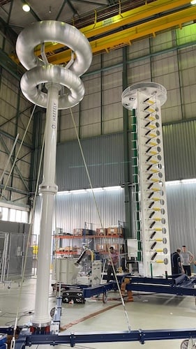
Figure 1. Mobile impulse test system. Image used courtesy of Pfiffner Group.
Power Frequency Withstand Tests Using Variable Frequency Supplies
To test equipment for power frequency insulation withstand, variable frequency supplies or resonant test sets are used to apply sustained 50/60 Hz voltages at elevated levels. These tests are governed by IEC 60060-3 and IEEE Std 4-2013, typically conducted at:
- 2.0 × Ur for 1 minute (where Ur is rated line-to-ground voltage),
- Or specified test levels derived from insulation coordination studies
For EHV and UHV systems, series resonance test sets are preferred due to their ability to deliver high voltages (up to 1200 kV) with minimal reactive power demand. The principle relies on forming a series LC circuit where:
$$f = \frac{1}{2 \pi \sqrt{LC}}$$
At resonance, the voltage across the test object can be controlled precisely, and the required excitation current is minimized. This allows testing of long cable runs, bushings, or GIS sections without excessive generator ratings.
Advantages of resonant systems include:
- Lower power consumption
- Clear waveform control
- Reduced overvoltage risk due to self-limiting resonance behavior
Test results are validated using RMS voltage measurements and insulation leakage current, which should remain stable and below pre-defined thresholds throughout the test duration.
Use of Oscillographic Recorders and Partial Discharge Measurement
While withstand tests confirm gross dielectric integrity, partial discharge (PD) measurements provide insight into incipient insulation defects that may not cause immediate breakdown but can degrade insulation over time. PD detection is particularly critical in solid and gas-insulated systems (e.g., cable joints, GIS spacers, epoxy bushings).
IEC 60270 defines the standard method for PD measurement, involving:
- A coupling capacitor (Ck) connected in parallel with the test object
- A measuring impedance (Zm) and high-frequency detector
- Output recorded as apparent charge in picocoulombs (pC)
PD activity is characterized by:
- Discharge inception voltage (PDIV)
- Discharge extinction voltage (PDEV)
- Maximum discharge magnitude, typically with a threshold of 5–10 pC for acceptable insulation
Modern systems use digital PD analyzers integrated with oscillographic recorders to plot phase-resolved PD patterns (PRPD), which help identify discharge sources (e.g., surface vs internal voids vs corona). For example, GIS spacers often exhibit internal PD due to air bubbles trapped during assembly; this would appear as repetitive pulses centered around the voltage zero-crossing in PRPD plots.
Additionally, UHF sensors or acoustic PD sensors are used for non-intrusive detection in energized GIS systems. These are particularly valuable for long-term monitoring or testing systems that cannot be de-energized easily.
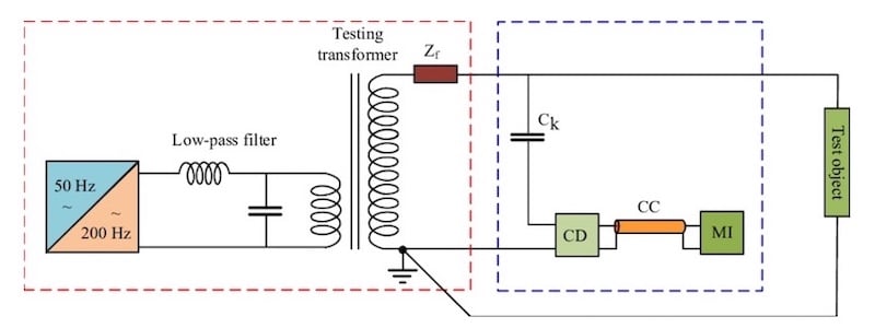
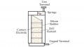
Figure 2. Schematic circuit of partial discharge test. Image used courtesy of ResearchGate.
MI : Measuring Instrument
CD : Coupling Device
Ck : Coupling Capacitor
CC : Measuring Cable
Zf : Blocking Impedance
| Test Method | Voltage Range | Purpose | Typical Standard |
| Impulse Testing | Up to 600 kV | Lightning/switching impulse withstand | IEC 60060-1/-2 |
| Power Frequency Withstand | Up to 1200 kV | AC voltage withstand (1 min) | IEC 60060-3, IEEE 4 |
| Partial Discharge Detection | >3 kV (PDIV typical) | Identification of internal insulation defects | IEC 60270 |
| Oscillographic Recording | Any | Waveform verification, PD pattern logging | Manufacturer-specific |
Table 1. Field test techniques and their purpose
Online Monitoring Techniques
As power systems become more digitized and the economic cost of unplanned outages escalates, online insulation monitoring is no longer optional—it is a foundation of asset health management. Online monitoring provides real-time diagnostic data under actual operating voltages and loads, enabling utilities to identify early signs of insulation degradation without de-energizing equipment.
The most impactful techniques include continuous partial discharge (PD) sensing, dielectric response monitoring (including tan δ analysis), and integration of this data within digital substations and SCADA systems for real-time predictive analytics.
Condition Monitoring of Insulation Using PD Sensors
Partial discharge is a direct indicator of insulation stress or defects and is most effective when monitored under normal service conditions. Online PD monitoring deploys permanently installed sensors such as:
- High-frequency current transformers (HFCTs) for cable terminations
- Ultra-high frequency (UHF) antennas embedded in GIS enclosures
- Coupling capacitors for transformer and rotating machine windings
PD activity in energized systems is non-destructive if detected early. It often precedes catastrophic failure by weeks or months. Online PD systems continuously track:
- PD magnitude (in pC)
- Discharge repetition rate (pulses/sec)
- Phase-resolved discharge patterns (PRPD) to locate the discharge source
Modern PD sensors operate within bandwidths of 300 kHz to several hundred MHz and use noise rejection algorithms to distinguish real signals from corona or switching noise. When integrated with machine learning classifiers, these systems can differentiate between internal void discharges, surface tracking, corona, and floating electrode phenomena.
GIS applications benefit significantly from UHF sensors, which detect fast-rising electromagnetic transients generated by internal discharges. These sensors are often embedded during manufacture and are connected to monitoring units via optical links for galvanic isolation.
Use of Dielectric Response and Tan Delta Measurements
In addition to PD, the dielectric response of insulation provides critical information about its moisture content, aging, and contamination. Tan delta (tan δ), or dissipation factor, measures the dielectric losses within insulation under service voltage and frequency. It is defined by:
$$\tan \delta = \frac{I_R}{I_C}$$
Where:
- IR: Resistive (loss) current
- IC: Capacitive current
A low tan δ (typically <0.005 for dry oil-paper insulation) indicates healthy insulation, while a rising tan δ suggests moisture ingress, insulation aging, or contamination by conducting particles. In power cables and transformers, online tan δ monitoring is possible through:
- Voltage divider tap signals (on bushings or cable terminations)
- Real-time measurement of current and voltage vectors
- Embedded dielectric sensors
Another technique—Frequency Domain Spectroscopy (FDS) or Dielectric Frequency Response (DFR)—extends tan δ analysis over a wide frequency range (1 mHz to 1 kHz). This reveals slow polarization phenomena caused by moisture or space charge accumulation. FDS is especially valuable in power transformers and bushings, where insulation degradation may remain undetected at power frequency alone.
Integration with Digital Substations and SCADA Systems for Predictive Maintenance
Modern insulation monitoring systems are integrated with IEC 61850-compliant digital substations, enabling real-time data transmission via substation LANs to centralized SCADA or asset management systems. These systems implement:
- Time-synchronized phasor data collection
- Remote diagnostics and alarms based on insulation stress levels
- Predictive analytics using historical trend data and AI models
Online condition monitoring devices output their data in structured protocols like GOOSE or MMS (Manufacturing Message Specification) for seamless SCADA integration. Key elements of predictive maintenance include:
- Threshold-based alarms for PD magnitude or tan δ rise
- Time-to-failure estimations using degradation models
- Event-triggered waveform capture for forensic analysis
A simplified representation of how these systems integrate can be visualized as:
| Subsystem | Function | Protocol / Interface |
| PD Sensor Array (GIS, cables) | Detects PD pulses | UHF / HFCT / Capacitive taps |
| Digital Analyzer | Filters and analyzes waveform and PRPD | Proprietary |
| SCADA / Asset Health Platform | Visualization, analytics, trend diagnostics | MMS, OPC-UA, Web dashboards |
| Maintenance System | Schedules inspections, creates work orders | ERP-integrated modules |
Condition-based maintenance (CBM) decisions—such as transformer oil processing, bushing replacement, or GIS SF₆ reconditioning—are now increasingly driven by these monitoring systems, enabling utilities to shift from reactive to proactive maintenance standards.
Key Takeaways
Field testing and online monitoring of high-voltage insulation systems are critical for maintaining the safety and reliability of modern power networks. These techniques not only verify the integrity of installations under real-world conditions but also enable early detection of hidden defects that could otherwise lead to costly outages or equipment failures.
By combining traditional withstand and impulse testing with advanced diagnostic methods like partial discharge detection, dielectric response analysis, and real-time SCADA integration, utilities gain a powerful framework for predictive maintenance. In practice, this ensures optimized asset performance, reduced downtime, and more efficient investment in grid infrastructure.
Featured image image used courtesy of Pfiffner Group.