Exploring Transformers With Dual-Voltage Ratings
This article explains transformers with dual-voltage ratings and explores their configurations and how the windings can be connected in series or parallel to achieve different voltage ratios.
Transformers with dual-voltage ratings operate with multiple H and X windings, each capable of handling distinct voltages. The configuration involves series or parallel connections of these windings, influencing the overall voltage output.

Image used courtesy of Adobe Stock
For instance, a transformer with dual-voltage ratings of 240 V and 480 V on H windings and 24 V and 48 V on X windings can be designated as 240 x 480 – 24 x 48. The transformer's voltage ratio is determined by how these windings are interconnected, with series connections combining voltages while parallel connections maintain the individual winding's voltage. This configuration allows flexibility in power supply and efficient management of different voltage demands. Additionally, the article covers power ratings of dual-voltage transformers and their associated winding connections.
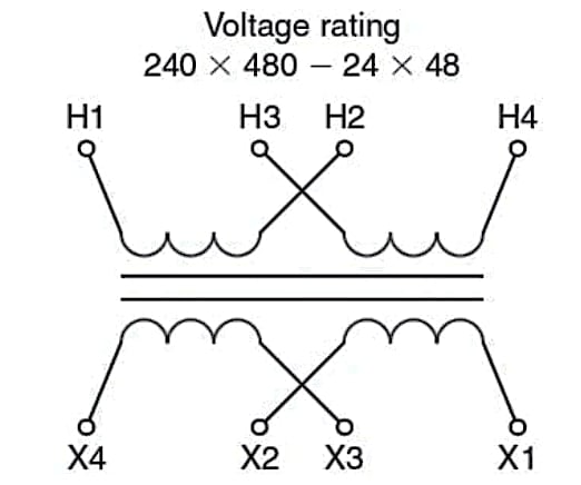
Some transformers may have more than one H winding and more than one X winding, but only one voltage may be used. The diagram in Figure 1 shows a common transformer configuration with two H windings and two X windings. This type of transformer is a dual-voltage rated transformer, and the voltage ratio depends on how the windings are connected.

Figure 1. A dual-voltage rated transformer with two H coils and two X coils. Image used courtesy of Ahmed Sheikh
Windings In Series and Parallel
If the transformer has dual-voltage ratings of 240 V or 480 V on the H windings and 24 V or 48 V on the X windings, the voltage rating would be designated 240 x 480 – 24 x 48. The lower of the two voltage ratings is always the rated voltage of one of the transformer windings alone. The H windings of this transformer would each be rated for 240 V. If we connect the two H windings in series, each winding can have 240 V across it for a total of 480 V across the two windings in series.
If we connect the two windings in parallel, each winding can have 240 V, but because they are in parallel, the total voltage across the two is 240 V. As a result, either 480 V or 240 V can supply the H windings, and the voltages across each will still not exceed the rated voltage of the winding. The voltage rating of this type of transformer is written 240 x 480. We would read this notation as "240 V or 480 V."
The same situation exists in the X windings. If each winding has enough turns so the voltage induced in it is 24 V, the two X windings in parallel will have 24 V across each winding and the two windings in parallel. If the two X windings are connected properly in series, then the 24 V of one winding will add to the 24 V of the second winding, and the total voltage across the two windings will be 48 V.
Transformer diagrams for dual-voltage transformers are usually drawn differently, as shown in Figure 2, making it easier to represent the connections for each voltage.

Figure 2. A standard diagram of a dual-voltage transformer. Image used courtesy of Ahmed Sheikh
Tech Tip: High-voltage connections are in series—odd to even numbers. Low-voltage connections are in parallel—even to even and odd to odd numbers.
The high-voltage connection for a dual-voltage transformer always requires that you connect the odd and even ends of the windings to make the series connection. The low-voltage connection always requires that the windings' even and odd ends are connected. In our example, if we had a supply of 480 V, you would connect H2 to H3 and then apply power to H1 and H4, as shown in Figure 3.

Figure 3. A dual-voltage transformer showing the H windings connected in series for the higher-rated voltage. Image used courtesy of Ahmed Sheikh
For a supply of 240 V, connect H1 and H3 and H2 and H4 and then apply power to both pairs. In Figure 4, it may not look like the two windings are in parallel, but this is just because of how the leads are represented in the diagram. The beginning of the two windings—H1 and H3—is on the left side, and the end of each windings—H2 and H4—is on the right side. The 240 V supply is connected to each winding—one of the 240 V supply wires is connected to H1 and the other to H2. The same is true for the H3 and H4 winding. The two windings are in parallel with the same supply voltage to each winding.

Figure 4. A dual-voltage transformer connected in parallel for the lower of the rated voltages. Image used courtesy of Ahmed Sheikh
Everything we have discussed regarding the H windings is also true of the X windings. For the higher voltage, connect X2 and X3 and then connect the load to X1 and X4. For the lower voltage, connect X1 and X3 and X2 and X4, and then connect the load to both pairs—that is, X1 and X3 and X2 and X4. Remember, the primary windings can be either the H or the X windings, depending on whether the transformer is a step-down or step-up transformer.
Transformer Connections for Three-Wire Systems
The secondary windings of a two-winding transformer may be connected in series, so not only are both ends of the windings available to be connected to the load but also the point where the two windings are connected in series. This is the neutral of the system. When connected this way, we have a three-wire, or dual-voltage, system. In this transformer connection, the output voltage is either twice the voltage of one winding or the voltage of one winding alone. If the transformer secondary windings each had a rating of 120 V, the voltage rating of such a transformer connection would be listed as 12/240, with the / indicating that the output voltage could be either 120 V or 240 V, with both voltages available at any time. Figure 5 shows a transformer with such a three-wire connection.

Figure 5. A transformer rated 480 – 240 / 120 supplying a three-wire system from a 480 V supply. Image used courtesy of Ahmed Sheikh
Tech Tip: The National Electrical Code requires the neutral point to be grounded if this can be done so that no point on the system has a potential of more than 150 volts to the grounded conductor.
The same dual-voltage three-wire system could also be created from a transformer with a voltage rating of 480 – 240 x 120, as long as a lead was connected to the point where X2 and X3 are connected and brought out from the transformer to be the neutral wire of the system.
Power Ratings for Dual-Voltage Transformers
The power rating in KVA is determined by the amount of current each winding is designed to carry at a rated voltage. In our example of a transformer with two different voltage ratings, the transformer's power rating is the same no matter which voltage we choose. However, the total current through the transformer must change to give the same power at different voltages. To deliver the same power when the lower-voltage rating is chosen, the total current is twice as large as the current that will flow when the higher voltage is selected. How can the same windings be designed to carry two different amounts of current without overheating?
Tech Tip: Different voltages of dual-voltage transformers do not change the maximum current requirements for each winding.
If we connect the windings for the higher-rated voltage, they are in series, so the total current through one winding is the same as the current through the other. With the same amount of power at the higher voltage, the current will be one-half as much as at the lower voltage.
When the windings are connected for the lower voltage, they are connected in parallel. The current through each of the parallel windings will be added together to give the total current of the transformer; each winding carries one-half the total current. As a result, at the lower voltage with the same amount of power, each winding has the same current carried at the higher voltage, but there will be twice as much total current as at the higher voltage. Figure 6 illustrates the current flow in series and parallel. The maximum current each winding can safely carry is the same in each case; they are the same windings whether connected in series or parallel.

Figure 6. Power is the same, and the coil carries no more than the maximum current in the parallel or series connection. Image used courtesy of Ahmed Sheikh
In the example, if the transformer has a power rating of 4.8 KVA, the H windings must be large enough to carry 10 amps at 480 V but also 20 amps at 240 V:
\[\frac{4.8KVA}{480V}=10\,amps\]
\[\frac{4.8KVA}{240V}=20\,amps\]
The current through each H winding would be 10 amps when they are connected in series for the high voltage. When connected in parallel for the low voltage, each winding would also carry 10 amps for a total of 20 amps at 240 V. The total power in each case is 4.8 KVA, and the total current each winding must be designed to carry is 10 amps—no matter which voltage connection is used.
Dual-Voltage Transformer Takeaways
Dual-voltage transformers are crucial in modern electrical systems, offering adaptability and efficiency in managing power supplies across varied voltage requirements. The ability to switch between different windings and voltages, achieved through series and parallel connections, makes these transformers versatile and highly valuable. They provide a practical solution for diverse applications, allowing seamless integration into systems where different voltage levels are necessary. By efficiently regulating and distributing power, dual-voltage transformers enhance operational flexibility and optimize energy utilization, making them an essential component in electrical engineering and power management.


