Facebook
 Google
 GitHub
 Linkedin
Primary Distribution Systems—Part 4: Fault Levels and Short Circuits
Learn about fault levels and short-circuit protection for medium-voltage distribution. We’ll examine current sources, fault types, symmetrical component calculations, and DER impact on coordination.
Primary distribution systems at medium voltage exist to move energy reliably from substation buses to feeders and laterals while keeping equipment stress and public safety within acceptable bounds. Among the most consequential design and operations tasks is establishing fault levels and short‑circuit behavior at key locations, then selecting and coordinating protection that can withstand and interrupt those currents.
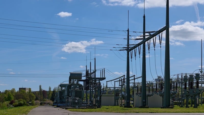
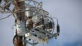
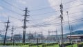
Figure 1. A high and medium voltage substation. Image used courtesy of Adobe Stock (licensed).
This article reviews where fault current comes from, how common distribution faults are represented and calculated, and how equipment ratings and coordination practices adapt—particularly as distributed energy resources (DER) change feeder conditions.
Fault Levels and Short‑Circuit Considerations
“Fault level” refers to the prospective short‑circuit current available at a location for a defined set of sources and system configurations. Planning studies typically bracket conditions with maximum and minimum cases to address interrupting duty, bus bracing, thermal/mechanical withstand, and relay sensitivity.
Ohm’s law applied to the Thevenin equivalent remains the foundation: the short‑circuit current equals the driving voltage divided by the equivalent source and network impedance between the source and fault. IEEE Std 141 describes this approach for industrial and distribution systems and explains why maximum and minimum studies are both needed to select interrupting devices and ensure protection sensitivity.
Beyond steady-state magnitudes, two additional aspects matter in practice:
X/R ratio and DC offset: The asymmetrical first‑cycle current includes a decaying DC component whose magnitude depends on the X/R ratio of the Thevenin network at the fault point. Equipment “close‑and‑latch” and momentary ratings therefore exceed pure symmetrical RMS values.
Time variation of rotating‑machine contributions: Synchronous and induction machines contribute subtransient, transient, and steady components with different time constants, which affects first‑cycle duty, interrupting duty at contact parting, and delayed‑tripping studies.
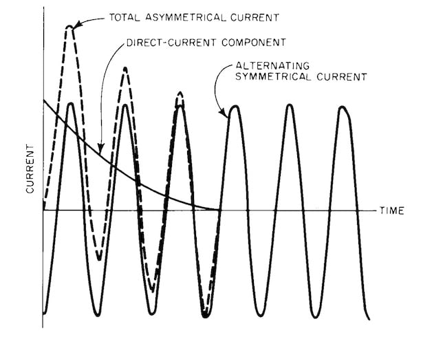
Figure 2. Typical system fault current. Image used courtesy of Protergia.
Sources of Fault Current
Substation Transformer Contribution
At a primary substation, the transformer and the upstream source are modeled as a Thevenin equivalent behind the transformer leakage impedance. The transformer’s nameplate percent impedance largely sets the available fault current on the medium‑voltage bus; higher percent impedance lowers the fault level. In short‑circuit studies using the 100 MVA method, transformer impedance is converted to the study base and combined with feeder and source impedances to compute “fault MVA,” which is then converted to amperes for device duty checks. A widely used relation on the 100 MVA base is:
$$\text{Fault MVA} = \frac{10,000}{\text{Reactance Percent on 100 MVA Base}}$$
This provides a direct path from aggregated percent reactance to initial symmetrical fault MVA at the study node.
Upstream Transmission System Contribution
The transmission system contributes through the substation transformer. System planners often specify an available short‑circuit level (in MVA) at the high‑voltage bus. That level is reflected through the transformer to the distribution side using the same 100 MVA method and series/parallel reductions to the point of fault, keeping track of X/R where peak and asymmetrical duties will be evaluated. Practical utility guidance of this process is detailed in distribution design manuals that align with IEC 60909 modeling assumptions.
Contribution From Distributed Generation
Synchronous generators (including synchronous motors operating as sources during faults) contribute high initial current governed primarily by direct-axis subtransient reactance Xd″. IEEE Std 141 explains the subtransient–transient–synchronous sequence used in protection studies; interrupting devices often see currents determined by Xd″ during the first cycles.
Induction machines contribute a short‑lived burst that decays quickly as the internal flux collapses after voltage is depressed by the fault. For short‑circuit calculations, an induction generator is treated similarly to an induction motor with only a subtransient term.
Inverter‑based DER (such as PV) typically limit current electronically. NREL’s Distribution Engineers Handbook notes that PV fault contribution is commonly about 1.1 times rated current, far below the multi‑per‑unit response of synchronous machines.
Types of Distribution Faults
Single Line‑to‑Ground (SLG) Faults
SLG events dominate on overhead feeders due to exposure of phase conductors to ground paths (through vegetation, wildlife, or hardware). These faults involve the positive, negative, and zero‑sequence networks in series, so the zero‑sequence return path—through earth, neutrals, and transformer grounds—strongly influences magnitude. In ungrounded or high‑impedance‑grounded systems, SLG current is intentionally limited, changing protection strategy.
Line‑to‑Line (LL) Faults
An LL fault couples the positive and negative sequence networks in parallel; zero sequence does not flow without a ground path. Magnitude typically falls between SLG and three‑phase values, depending on local impedances.
Double Line‑to‑Ground (DLG) Faults
DLG faults connect two phases to ground and couple all three sequence networks but with a parallel‑series interconnection that differs from SLG. Resulting currents can exceed SLG when the zero‑sequence network is low‑impedance.
Three‑Phase Faults
A bolted three‑phase short is symmetrical and involves only the positive‑sequence network. Although less common on feeders, it usually produces the highest symmetrical current, setting many equipment interrupting duties.
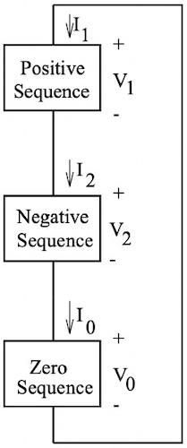
Figure 3. Sequence connection for a single line‑to‑ground fault. Image used courtesy of LibreTexts.
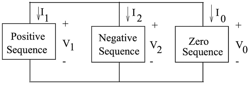
Figure 4. Sequence connection for a double line‑to‑ground fault. Image used courtesy of LibreTexts.
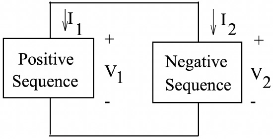
Figure 5. Sequence connection for a line‑to‑line fault. Image used courtesy of LibreTexts.
Short‑Circuit Calculations
Accurate maximum and minimum fault levels are required for:
- Equipment rating checks (momentary/interrupting/making duties).
- Protection coordination (ensuring devices operate in the intended order).
- Sensitivity and reach (especially for high‑impedance faults or remote sections).
- Grid modernization with DER, where fault levels can vary by topology and operating state.
IEEE Std 141 discusses these purposes to model machine subtransients for first‑cycle duty versus later‑cycle values for time‑delayed functions.
Use of Symmetrical Component Analysis
For unbalanced shunt faults, the symmetrical components method connects the positive (Z1), negative (Z2), and zero (Z0) sequence networks according to the fault type.
For an SLG fault with Thevenin voltage Eph:
$$I_1 = I_2 = I_0 = \frac{E_{ph}}{Z_1 + Z_2 + Z_0}$$
The total SLG fault current is given by:
$$I_F = I_1 + I_2 + I_0 = \frac{3E_{ph}}{Z_1 + Z_2 + Z_0}$$
For an LL fault with Thevenin voltage Eph:
$$I_1 = \frac{E_{ph}}{Z_1 + Z_2}~,~I_2 = -I_1~,~I_0 = 0$$
The total LL fault current is given by:
$$I_F = \sqrt{3}I_1 = \frac{\sqrt{3}E_{ph}}{Z_1 + Z_2}$$
These expressions arise from the standard series/parallel connections of the sequence networks and are presented in utility design manuals that reference symmetrical components theory for distribution applications.
Balanced (three‑phase) faults are often estimated with the IEC 60909 initial symmetrical current formula:
$$I_k^{''} = \frac{c ~ \times ~ U_n}{\sqrt{3}~\times~Z_k}$$
where c is the voltage factor (commonly 1.0–1.1 by system level), Un is the nominal system voltage (kV), and Zk is the short-circuit impedance (ohms) from source to fault. This relation provides a consistent way to calculate initial symmetrical three‑phase fault currents for duty assessment.
Impact of Conductor Impedance and Transformer Impedance
Feeder impedance accumulates with distance; fault current declines as the fault moves away from the source. Positive/negative‑sequence impedances are similar for lines and transformers, while zero‑sequence impedance depends on grounding and return paths, including earth resistivity and metallic neutrals. For maximum short‑circuit estimates, IEC 60909 guidance uses conductor resistance at lower reference temperature (such as 20 °C), while minimum‑current cases use higher resistance reflecting heating, yielding different protection margins.
Transformer leakage impedance from the nameplate is a first‑order driver of fault level; on the 100 MVA base, percent impedances convert to a single equivalent used to derive fault MVA and current.
Equipment Rating and Protection
Interrupting Capacity of Circuit Breakers and Reclosers
Distribution‑class circuit breakers are specified by symmetrical interrupting rating at a given maximum rated voltage, along with close‑and‑latch (momentary) and 3‑second short‑time ratings that account for asymmetrical duty. Applying these ratings requires translating the calculated symmetrical RMS fault current to the applicable duty using the system X/R ratio to account for DC offset and peak crest. IEEE application and rating standards establish how X/R modifies duty and how service conditions, reclosing, and transient recovery voltage (TRV) affect selection.
Reclosers apply similar concepts with device‑specific momentary and making capabilities. Their fast and delayed curves, dead times, and reclose sequences are selected per IEEE C37.104 guidance to balance temporary‑fault clearing against permanent‑fault isolation and coordination with downstream devices.
Fuse Coordination with Fault Levels
Coordinating fuses with upstream reclosers or breakers relies on time‑current characteristic (TCC) separation under both maximum and minimum fault currents. Current‑limiting fuses must be applied within their interrupting rating, considering asymmetry. High‑voltage fuse application and design‑test standards (IEEE C37.41 and C37.42) define interrupting performance, pre‑arcing and total‑clearing zones, and how to interpret let‑through energy for thermal and mechanical duty on downstream equipment. These documents are the basis for selecting link ratings, verifying duty with available feeder fault levels, and ensuring selectivity with upstream recloser fast/slow curves or sectionalizing strategies.
Impact of DER on Fault Current Magnitude and Coordination
Widespread DER changes both the magnitude and directionality of short‑circuit infeed:
Inverter‑interfaced DER: Grid‑following inverters typically limit current to near rated levels; common limits are typically in the range of approximately 1.0–1.2 per unit (p.u.) of of rated current with short durations, which can reduce fault levels on lightly fed sections, potentially compromising traditional overcurrent sensitivity. Conversely, coordinated grid‑forming control can be designed for higher short‑term current to support legacy protection in islanded operation, but such behavior is not universal and remains manufacturer‑specific. Short‑circuit studies for feeders with high inverter penetration therefore evaluate both maximum and minimum duty scenarios and verify pickup/coordination across these ranges.
Machines-based DER: Machine‑based DER increases local fault current, especially for nearby faults, and can affect recloser and fuse coordination windows. Induction motors and generators contribute significant current for a few cycles as stored air‑gap flux collapses; manufacturer guides provide approximations (for example, initial contributions on the order of a few multiples of full‑load current for the first half‑cycle to several cycles). This momentary infeed must be considered in device momentary and making duty.
Many Factors in the Mix
Primary distribution fault levels are shaped jointly by substation transformer impedance, upstream grid strength, feeder impedance to the fault point, and local sources including DER. Unbalanced faults dominate in overhead distribution, and symmetrical components remain the standard analytical framework for calculating currents and guiding protection.
Equipment must be checked for both symmetrical interrupting and asymmetrical momentary duty, with X/R‑based multipliers applied where required. As DER penetrations increase, two effects commonly appear: modest but non-negligible increases in available fault current from many small inverters, and more substantial first‑cycle duty where synchronous DER is present.
Both can desensitize upstream relays, challenge fuse interrupting ratings, or disturb long‑standing recloser‑fuse practices—requiring updated short‑circuit studies, TCC revisions, and sometimes changes to grounding or sectionalizing. Consistent modeling of X/R for duty translation, attention to maximum/minimum scenarios, and explicit treatment of DER behavior allow accurate rating, setting, and coordination of primary distribution assets.