Facebook
 Google
 GitHub
 Linkedin
High-Voltage Testing and Insulation Coordination—Part 2
Here, in Part 2, we examine insulation coordination and Basic Insulation Level (BIL) in high-voltage systems for reliability against transient overvoltages.
In Part 1 of this series, we kicked off our exploration of high-voltage insulation coordination with a look at the nature of overvoltages, standardized impulse and withstand voltage testing methods, and the role of standards for reliability.
Now, In Part 2, we discuss the principles and practical implications of insulation coordination and Basic Insulation Level (BIL) in high-voltage systems, including standardized ratings, equipment design considerations, and environmental correction factors. It also addresses the role of BIL in ensuring system reliability against transient overvoltages such as lightning and switching surges.
The Basic Insulation Level (BIL) is a standardized metric used to define the insulation strength of electrical equipment against transient overvoltages, specifically high-magnitude surges such as lightning impulses. Defined in terms of a peak voltage value with a standardized waveform, BIL serves as a benchmark for the dielectric design of components like transformers, bushings, switchgear, and surge arresters. It represents the peak voltage that insulation can withstand without breakdown during a standard lightning impulse test, usually defined with a 1.2/50 μs waveform.
The BIL rating is not derived from continuous operational voltages but from impulse withstand testing and is always significantly higher than the system’s nominal operating voltage. Its primary purpose is to ensure that equipment can tolerate transient overvoltages without dielectric failure. This level is set with a statistical safety margin that accounts for manufacturing tolerances, installation variability, environmental conditions, and the inherent non-deterministic nature of insulation breakdown under impulse stress.
Concept of Basic Insulation Level (BIL)
BIL is formally defined in both IEC 60071-1 (Insulation coordination – Definitions, principles, and rules) and IEEE C62.82.1 (Standard for Insulation Coordination – Definitions, Principles, and Rules). These standards provide a coordinated framework for specifying the required insulation levels based on system voltage, expected overvoltage magnitudes, protective device response times, and acceptable failure probability.
BIL versus Other Insulation Levels
It is important to distinguish between BIL, Basic Switching Impulse Level (BSL), and Continuous Operating Voltage (Un):
- BIL: Rated impulse level for lightning transients (1.2/50 μs), expressed in kV (peak).
- BSL: Used for high-voltage equipment (usually ≥300 kV) where switching surges dominate; waveform is typically 250/2500 μs.
- Power-Frequency Withstand: 50/60 Hz applied for 1 minute; not to be confused with BIL but also part of total insulation coordination.
Together, these levels form a graded insulation structure, with BIL acting as the upper bound for equipment subject to atmospheric overvoltages.
Standard BIL Ratings by System Voltage
To ensure uniformity, both IEC and IEEE define standardized BIL values that correspond to nominal system voltages. These standardized BIL levels are rounded values selected for coordination with surge arresters and physical clearance requirements. A simplified excerpt from the IEEE standard (C62.82.1) is shown in Table 1.
| System Voltage (kV, RMS) | Standard BIL (kV, peak) |
| 4.16 | 60 |
| 13.8 | 95 |
| 34.5 | 150 |
| 69 | 350 |
| 115 | 550 |
| 230 | 900 |
| 345 | 1050 |
| 500 | 1425 |
| 765 | 2100 |
Table 1. System voltages and corresponding BIL values
For example, a 230 kV class transformer may be rated with a BIL of 900 kV. This implies that during a standardized 1.2/50 μs lightning impulse test, the insulation must withstand a peak voltage of 900 kV without flashover or internal breakdown.
Role of BIL in Equipment Design
BIL directly informs the clearance distances, creepage distances, and physical insulation geometry in high-voltage design. For example, the spacing between windings, conductor-air gaps in switchgear, and the oil or SF₆ dielectric path must be designed to handle the rated BIL plus a safety factor. Furthermore, coordination with surge protective devices (SPDs) such as metal-oxide varistors (MOVs) ensures that BIL levels are never exceeded in service.
In transformer design, BIL influences:
- Inter-turn insulation thickness
- Winding-to-core and winding-to-ground spacings
- Bushing insulation type and geometry
- Impulse shielding design, especially for regulating and tertiary windings
Additionally, the BIL rating affects factory acceptance testing (FAT) and must be verified through impulse withstand tests, either as full-wave or chopped-wave tests. Transformer manufacturers design internal impulse voltage distribution using simulation tools to ensure that the peak stress remains within material limits even under highly non-uniform fields caused by winding interleaving or core geometry.
BIL selection is also fundamental to insulation coordination studies, which balance the insulation strength of equipment against the protective capability of SPDs. The guiding principle is that surge arresters should clamp the voltage to below BIL values, providing an adequate protective margin typically on the order of 15–20%.
Insulation Coordination Fundamentals
Insulation coordination is the process of ensuring that the insulation of electrical equipment can withstand the overvoltages likely to occur during the system’s lifetime, without exceeding economically and operationally justified limits. This requires a strategic balance between the insulation strength of system components and the surge protection strategy, ensuring reliability without excessive overdesign. It is governed by international standards such as IEC 60071-1, IEEE C62.82.1, and the companion guides for equipment-specific insulation design.
Coordination (Protective) Margin and Protective Level
A key parameter in insulation coordination is the protective margin, which is defined as the difference between the insulation withstand voltage (typically BIL for lightning impulses or BSL for switching surges) and the maximum temporary or transient overvoltage that may appear at a given point in the system. The general principle is:
Protective Margin = Insulation Withstand Level - Maximum Expected Overvoltage
To ensure a conservative and statistically robust design, standards typically recommend a minimum protective margin of 15–20%. This means that surge protective devices—such as arresters—must limit transient overvoltages to values below the BIL of the connected equipment, even under worst-case operating conditions.
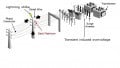
These voltages are characterized by their probability of occurrence, which varies based on location, system topology, and switching behavior. For example, lightning impulses are characterized using a 1.2/50 μs waveform and a statistical breakdown probability of 2%, whereas switching impulses typically use a 250/2500 μs profile and assume longer-duration stress on insulation.
The protective level of arresters is denoted by the residual voltage they allow to pass, which must be coordinated with BIL values to avoid insulation breakdown. For example, if the BIL of a 230 kV transformer is 900 kV, the arrester at its terminal should have a residual voltage no greater than ~750–765 kV (based on 15–20% margin).
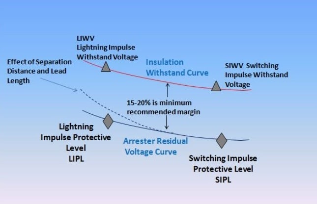
Figure 1. Design standards recommend a minimum protective margin of 15–20%. Image used courtesy of INMR.
Insulation Strength vs Surge Withstand Capability
Insulation strength refers to the ability of a material or dielectric system to withstand electric stress without breakdown. However, in high-voltage systems, the insulation strength must be evaluated not just as a material property but in terms of surge withstand capability, which involves:
- The spatial electric field distribution
- Impulse response under non-uniform voltage gradients
- Dielectric interfaces (such as oil–paper, SF₆–epoxy)
- The impact of multiple reflections and traveling waves in complex geometries
Because overvoltages occur as traveling surges, local peak voltages may be higher than predicted steady-state levels. Surge reflections at impedance mismatches can result in voltage doubling at open ends or poorly matched interfaces. For this reason, insulation is rated not only for its nominal field stress but also for transient overstress scenarios.
Classification of Insulation Systems
The standards define different insulation classes depending on the location, restore-ability, and physical exposure of the insulation system, as shown in Table 2.
| Insulation Type | Definition | Typical Examples |
| Internal Insulation | Located inside equipment and inaccessible to external influences | Transformer windings, breaker interrupters |
| External Insulation | Exposed to environmental conditions like rain, pollution, or humidity | Bushings, insulators, air gaps |
| Self-Restoring | Can recover original dielectric strength after flashover or discharge | Air gaps, SF₆ insulation |
| Non-Self-Restoring | Cannot restore dielectric strength without human intervention or repair | Oil–paper systems, epoxy resin insulation |
Table 2. Definitions of different classes on insulation types
The classification affects both testing protocols and design choices. For instance, non-self-restoring insulation must never experience a flashover during operation or testing, while self-restoring insulation can tolerate surface flashover under controlled conditions, provided it doesn’t damage the equipment or compromise reliability.
Phase-to-Ground, Phase-to-Phase, and Longitudinal Insulation
Insulation levels differ depending on the mode of stress application:
- Phase-to-Ground Insulation: Most critical in overhead systems; must withstand lightning impulses and switching surges. Rated using BIL or BSL.
- Phase-to-Phase Insulation: Relevant in closely spaced conductors, GIS systems, and multi-phase windings. Usually stressed during internal fault or ferroresonance conditions.
- Longitudinal Insulation (or differential insulation): Appears along the winding or conductor itself, significant in surge propagation studies.
IEC 60071 recommends separate coordination evaluations for each of these insulation paths, especially in the presence of non-uniform electric field gradients. For example, in a three-phase transformer, phase-to-phase clearances may require a different design envelope than phase-to-ground, particularly if surge arresters are only applied at the line terminals.
In GIS and GIL systems, where physical clearances are minimized, the coaxial geometry introduces high capacitance and complex surge interactions, requiring precise modeling of both internal dielectric interfaces and transient voltage sharing across phases and lengths.
Practical Design Implications
The Basic Insulation Level (BIL) selected for high-voltage equipment is not just a nominal rating—it directly governs the dimensional, structural, and dielectric design of components exposed to transient overvoltages. BIL determines critical attributes such as creepage distances, air clearances, and the need for surge shielding or arresters.
In practical system design, particularly for EHV and UHV systems (132 kV and above), the translation of BIL into physical design metrics must also account for environmental corrections and the coordination of multiple equipment classes operating at different voltage levels.
BIL and Its Impact on Clearance and Creepage Design
Clearance distance is the shortest path through air between two conductive parts, or between a conductive part and ground. For a given system voltage, the required clearance increases with higher BIL, as the insulation must withstand peak transient voltages without flashover.
The correlation between BIL and required phase-to-ground clearance in air-insulated switchgear (AIS) is standardized by IEC and IEEE guides. For instance, based on IEC 60071-2, the minimum clearance for a 400 kV BIL of 1425 kV is approximately 3.1–3.4 meters under standard atmospheric conditions. This value ensures that the system withstands the 1.2/50 μs impulse waveform without breakdown.
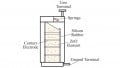
Creepage distance, in contrast, is the shortest path along an insulating surface. It is crucial in environments subject to contamination or moisture. While BIL governs clearance (impulse withstand), creepage distances are tied to system voltage and pollution severity, and are calculated independently using:
Creepage Distance = System Voltage (rms) x Creepage Factor (mm/kV)
Creepage factors range from 16 mm/kV (light pollution) to 31 mm/kV (very heavy pollution), per IEC 60815. However, components with higher BIL often end up with longer creepage distances simply because their physical size increases (Table 3).
| System Voltage (kV) | Typical BIL (kV) | Min Air Clearance (m) | Creepage Distance (mm/kV) |
| 132 | 550 | ~1.0 | 22–31 |
| 400 | 1425 | ~3.1–3.4 | 31–50 |
| 765 | 2100 | >5.0 | ≥50 |
Table 3. Typical clearances and creepage distances vs. BIL
These values vary based on system insulation philosophy (AIS vs GIS), equipment design, and environmental derating.
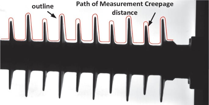
Figure 2. Creepage distance over transmission line insulator. Image used courtesy of Springer Nature.
Altitude and Pollution Correction Factors
All standard BIL values assume standard atmospheric pressure (101.3 kPa) and sea-level conditions. However, installations at altitudes above 1000 meters require a derating of dielectric strength due to reduced air density, which weakens insulation withstand.
According to IEC 60071-2, the altitude correction factor (Ka) is applied to both clearances and test voltages:
$$K_a = e^{\frac{m(h-1000)}{8150}}$$
Where
- h Altitude above sea level in meters
- m Exponent depending on voltage type (typically 1 for Lightning impulse and Switching impulse)
For instance, at 2000 m, Ka ≈ 1.27, indicating a 27% increase in required clearance or test voltage.
Similarly, pollution correction affects creepage distance. Per IEC 60815, the environmental conditions are classified into four levels:
| Pollution Level | Minimum Nominal Specific Creepage Distance (mm/kV) |
| I – Light | 16 |
| II – Medium | 20 |
| III – Heavy | 25 |
| IV – Very Heavy | 31 |
These factors affect the sizing and selection of bushings, insulators, and surge protection placement. Design engineers must consult pollution maps or conduct site-specific contamination testing to determine the proper correction level.
Equipment Coordination Across Voltage Levels
As power systems are rarely monolithic, coordination across different voltage levels—especially in transmission corridors that step between 132 kV, 220 kV, 400 kV, and 765 kV—is essential. Each voltage level has a standardized BIL defined by IEC 60071-1 and IEEE C62.82.1, but transition zones (such as transformer windings or circuit breakers interfacing two systems) require close coordination.
For example, a 400/132 kV transformer must have its high-voltage winding rated for a BIL of 1425 kV, while its 132 kV winding will be rated for 550 kV. Surge arresters are installed at both ends to clamp transients and maintain insulation coordination. The BIL gap between the two sides must also consider transferred overvoltages via capacitive or inductive coupling.
In UHV systems (such as 765 kV), coordination challenges are magnified by the scale of clearances and the limited test voltage capabilities of laboratory equipment. In such cases, statistical insulation coordination using probability-based models (such as 2% failure probability) is applied in lieu of direct impulse withstand testing.
GIS and HVDC systems further complicate this picture. GIS uses smaller physical clearances and relies on SF₆ dielectric strength, but must match BILs of external AIS components. HVDC insulation design, on the other hand, requires DC withstand, switching impulse, and lightning impulse coordination, which follow different waveforms and aging mechanisms.
Key Takeaways
Insulation coordination and the accurate specification of Basic Insulation Level (BIL) are foundational to the safe and reliable operation of high-voltage power systems. These concepts directly impact the design, selection, and installation of critical infrastructure—such as transformers, circuit breakers, surge arresters, and switchgear—ensuring that insulation strength aligns with the highest overvoltage stresses a system may encounter.
Proper coordination minimizes the risk of flashover, equipment damage, and service interruption, especially under conditions involving lightning surges, switching operations, or temporary overvoltages. Additionally, factoring in environmental conditions—such as altitude, pollution severity, and atmospheric pressure—ensures that installed equipment performs as intended across diverse geographic regions.