Facebook
 Google
 GitHub
 Linkedin
High-Voltage Testing and Insulation Coordination—Part 3
In this article, we’ll teach you about lightning, switching, and temporary overvoltages in high-voltage systems, detailing their origins, characteristics, and mitigation strategies.
Lightning remains one of the most significant sources of external overvoltage stress on high-voltage power systems, particularly in overhead transmission networks. These surges, characterized by extremely fast front times and high peak amplitudes, can cause insulation breakdown, flashovers, and equipment damage if not properly mitigated.
A comprehensive understanding of lightning surge behavior—including the modes of incidence, interaction with system components, and statistical performance metrics—is foundational to effective insulation coordination and system protection.
Lightning Surges: Direct Strikes vs Back Flashover
Two primary mechanisms govern how lightning interacts with power lines: direct strikes to phase conductors and induced back flashovers from tower structures.
- Direct strikes occur when a lightning leader connects directly to a phase conductor. The resultant surge travels along the line in both directions with amplitudes that can exceed 200 kV/μs in rate of rise and peak values up to several hundred kilovolts. The surge waveform approximates a 1.2/50 μs impulse, consistent with standardized testing.
- Back Flashover, however, is often the dominant cause of lightning-induced outages in high-voltage networks. It occurs when a lightning strike hits the grounded tower or shield wire, raising the tower potential significantly due to the tower footing resistance (Rt). This potential rise appears across the tower insulators; if the resulting voltage exceeds their BIL, a flashover from the tower to phase conductor ensues. The critical voltage (Vbf) for back flashover is given by:
$$V_{bf} = I_{ltg} \cdot R_t~+~\frac{di}{dt} \cdot Z_t $$
Where:
- Iltg is the lightning current (kA)
- Rt is the tower footing resistance (Ω)
- dI/dt is the rate of current rise
- Zt is the tower surge impedance (typically 100–200 Ω)
Reducing Rt and employing shield wires or counterpoise grounding are standard practices to mitigate back flashover risk.
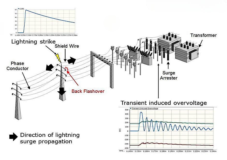
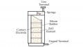
Figure 1. Direct lightning strike vs. back flashover. (Click on imagte to enlarge) Images used courtesy of PS CAD.
Tower Footing Resistance and Surge Impedance
Tower footing resistance (Rt) is a critical parameter in lightning performance. It determines the potential rise during a ground strike and is influenced by soil resistivity, grounding electrode design (such as rods, rings, counterpoise), and moisture content. IEEE Std 80 recommends maintaining Rt below 10 Ω for high lightning exposure areas, though in rocky terrain this is often difficult.
The surge impedance of transmission structures also affects the transient voltage distribution. While conductors typically have surge impedances of 300–400 Ω, a lattice tower may have Zt ≈ 100–150 Ω. This impedance mismatch affects surge reflection and transmission at discontinuities, impacting the propagation of lightning surges along the line.
Lightning Performance Metrics
Lightning performance of overhead lines is quantified by two key statistical measures:
- Strokes per year – The expected number of lightning strokes incident on a given line section per year, typically estimated using:
$$N_g = W_{eff} \cdot GFD \cdot L$$
Where:
- Weff = effective collection width of the line (km), based on shielding and tower geometry
- GFD = ground flash density (strokes/km²/year)
- L = line length (km)
Typical GFD values range from <1 stroke/km²/year (temperate zones) to >15 in tropical regions (such as Malaysia, Congo). This difference is due to the increased frequency of thunderstorms in tropical areas.
- Outage rate per 100 km/year – The number of flashover-induced outages per 100 km of line per year. This is computed via statistical surge analysis or simulation tools (such as EMTP, ATPDraw) and validated against field data.
Table. Typical Lightning Performance by Voltage Level
| System Voltage | Shielded? | Outage Rate (flashovers/100 km/year) |
| 132 kV | Yes | 1.0 – 3.0 |
| 220 kV | Yes | 0.5 – 1.5 |
| 400 kV | Yes | <0.3 |
| 765 kV | Yes | <0.1 |
Improved performance at higher voltages is due to greater BIL, better shielding design, and lower Rt. However, accurate modeling of shielding angles, lightning stroke currents (often modeled using Heidler function), and tower grounding are essential for reliable surge protection.
Switching Surges and Temporary Overvoltages (TOVs)
While transient overvoltage protection in distribution and sub-transmission systems is primarily driven by lightning surges, switching surges become the primary concern at EHV and UHV levels (≥300 kV). Unlike the fast-rising, high-frequency impulses of atmospheric origin, switching overvoltages are generally slower in rise (10–2500 μs), longer in duration, and more systemic—arising from internal circuit operations such as line energization, fault clearing, and load rejection.
Their waveform characteristics, origin mechanisms, and potential to exceed Basic Insulation Level (BIL) during certain system states make them central to insulation coordination studies, particularly in systems operating above 245 kV.
Origin of Switching Surges
Switching surges arise from various normal and abnormal network operations, each producing distinctive overvoltage profiles:
- Energization of long transmission lines: When an unloaded EHV line is energized, voltage waves are launched toward the open end and reflected back. The mismatch in surge impedance at the open end causes partial or full reflections, leading to constructive interference and transient overvoltages. These may reach up to 2.0–2.5 pu of rated voltage if not mitigated by controlled switching or pre-insertion resistors.
- Reclosing operations: After fault isolation, reclosing the circuit without synchronization may inject a surge due to trapped charges on the line capacitance. The voltage difference between the trapped charge and the source can result in transient overvoltages, particularly harmful for transformers and GIS equipment.
- Fault clearing and current chopping: In vacuum and SF₆ circuit breakers, rapid interruption of low inductive currents (such as transformer magnetizing current) leads to steep rate-of-change of current (di/dt) and voltage oscillations. This effect is known as current chopping, often modeled using surge networks with equivalent capacitance and inductance.
- Load rejection: Sudden disconnection of a large inductive or capacitive load can result in traveling wave oscillations. In lightly loaded systems, the lack of damping can prolong the transient, creating the potential for temporary overvoltage (TOV) conditions.
Temporary Overvoltages (TOVs)
TOVs differ from switching surges in that they persist for longer durations—typically milliseconds to several minutes—and originate from power-frequency phenomena rather than high-frequency transients. These include:
- Resonance phenomena:
- Series resonance between line inductance and shunt capacitance during open-end conditions may amplify voltages at the receiving end.
- Ferroresonance, a nonlinear resonance between saturable inductors (such as transformer cores) and system capacitance, is particularly hazardous in ungrounded systems or during single-pole switching. The resulting TOVs can be sustained and difficult to extinguish without de-energization.
- Fault recovery transients: Following the clearing of a ground fault, especially in compensated or resonant-grounded systems, transient recovery voltages (TRVs) may appear across circuit breakers and line insulation. Their amplitude and shape depend on fault location, network configuration, and grounding scheme.
- Open conductor or neutral displacement: In unbalanced systems, such as those operating with isolated neutrals, a phase-to-ground fault can elevate the healthy-phase voltages significantly above nominal. This is a critical scenario for insulation coordination in medium-voltage distribution and cable systems.

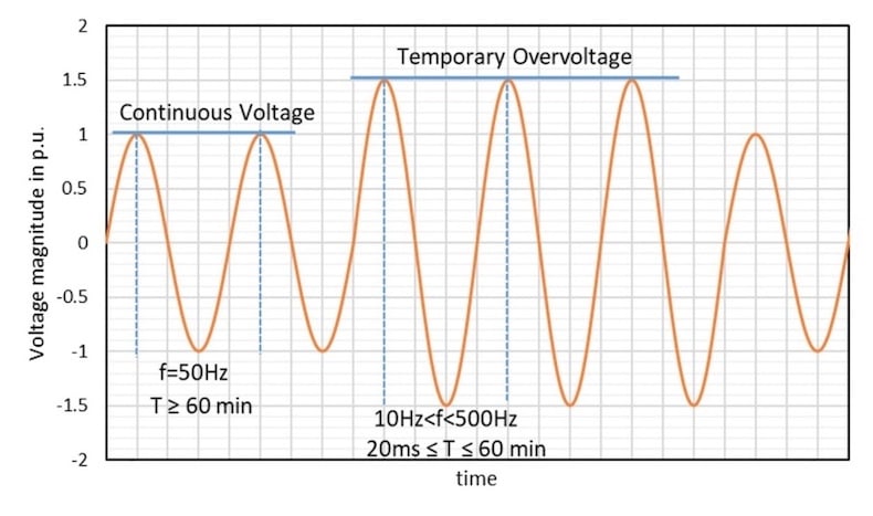
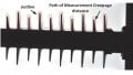
Figure 2. Temporary Overvoltage. Images used courtesy of CIGRE UK.
Severity and Waveform Comparison
Switching surges are typically represented by a 250/2500 μs impulse waveform per IEC 60060-1 for HVDC and UHV AC systems. Their longer duration, compared to the 1.2/50 μs waveform for lightning, poses different challenges for insulation design. Equipment such as GIS, transformers, and bushings are more sensitive to switching surges due to their dielectric response characteristics.
| Characteristic | Lightning Surge | Switching Surge | Temporary Overvoltage (TOV) |
| Typical front time | 1.2 μs | 100–250 μs | >20 ms |
| Duration (half-value time) | 50 μs | 1000–2500 μs | 100 ms to >1 s |
| Source | External (atmospheric) | Internal (switching) | Internal (resonance, faults) |
| Frequency content | 100 kHz – 1 MHz | 1–10 kHz | 50/60 Hz |
| Typical peak amplitude | >500 kV | 1.5–2.5 pu | 1.1–1.8 pu (sustained) |
Unlike lightning impulses, switching overvoltages tend to be more repetitive, occur in clusters (such as multiple switching attempts), and require energy-handling capability in protective devices like surge arresters.
Effective mitigation strategies include:
- Controlled switching (timed circuit breaker operation)
- Surge arresters with tailored energy ratings
- Pre-insertion resistors or capacitors for line energization
- Transformer surge capacitors to damp high-frequency transients
All insulation coordination studies above 245 kV must account for switching surge withstand levels (SIWL), often tested with standard impulse shapes in accordance with IEC 60071-1 and IEEE C62.82.1.
Key Takeaways
Understanding lightning surges, switching surges, and temporary overvoltages is essential for ensuring the reliability, safety, and longevity of high-voltage power systems. These phenomena directly influence insulation design, equipment selection, grounding practices, and protective device coordination, all of which are critical for minimizing outages, preventing costly equipment failures, and maintaining stable system operation.
By integrating accurate modeling, adherence to standards, and effective mitigation strategies, system resilience and performance in real-world operating environments can be enhanced.