Facebook
 Google
 GitHub
 Linkedin
Introduction to Inductor Filter Types and Applications
A frequency filter is a circuit that passes certain frequencies and reduces signal levels at other frequencies. Learn about various types of inductive filters and their power and communication systems applications.
A filter blocks unwanted signals or noise voltages and passes wanted signals with little or no attenuation. Filters are usually classified according to frequency characteristics; a low-pass filter passes low-frequency signals and attenuates all frequencies above a selected cutoff frequency. Similarly, a high-pass filter passes only those inputs with frequencies above the selected cutoff frequency. A bandpass filter passes signals within a selected frequency band, and a notch (or band-stop) filter blocks frequencies within its band.
Frequency filters are used to eliminate harmonics. Power lines also pick up interference (noise) caused by lightning strikes and machine-made radiation from devices like high-power transmitters or radiation devices. This type of interference can cause problems with other types of devices that may be on the line. Frequency filters are used to remove these undesirable signals.
Basic Types of Inductive Filters
The functions of various types of filters are illustrated by the waveforms and typical frequency response graphs below.
Low-Pass Filters
A low-pass frequency filter is a filter that allows all frequencies below a selected frequency to be applied to a load and blocks all frequencies above that point, as shown in Figure 1. The simplest filters consist of an inductor connected in series with a load. Low-pass filters are typically used in DC power and audio applications.
At 0 Hz, an inductor has zero reactance, and the total source voltage is across the load. Under this condition, there is maximum current flow through the load. As frequency increases, reactance increases in direct proportion. Some source voltage is dropped across the inductor, reducing current flow through the load.
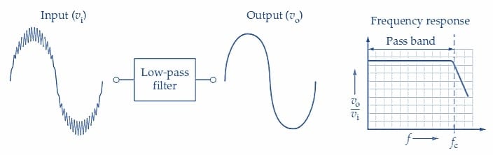
Figure 1. Waveforms and frequency response for a low-pass filter. Image used courtesy of Amna Ahmad
The input waveform for the low-pass filter in Figure 1 is composed of a low-frequency signal with an unwanted high-frequency input superimposed. The low-frequency input is reproduced at the output with very little attenuation, while the high-frequency noise voltage is severely attenuated.
The gain/frequency response graph for the filter is a graph of vo/vi plotted versus frequency (f). As illustrated in Figure 1, the filter has a low-frequency pass-band where the output voltage approximately equals the input (vo/vi≈1). The pass-band applies to all signal frequencies from zero up to the cutoff frequency. For input frequencies above the cutoff frequency, vo/vi is less than one and rapidly falls off to lower values. So, as shown by the graph, signals with frequencies above fc are attenuated.
High-Pass Filters
The high-pass filter in Figure 2 passes high-frequency input voltages and attenuates low-frequency inputs. In this case, the pass-band is above the cutoff frequency (fc), and the attenuation band is below fc. So, low-frequency inputs are attenuated while high-frequency signals are passed to the output terminals. Like low-pass filters, combinations of inductive-resistive-capacitive circuits are designed for this purpose.
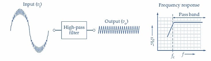
Figure 2. Waveforms and frequency response for a high-pass filter. Image used courtesy of Amna Ahmad
The simplest of these filters is an inductor in parallel with a load. High-pass filters are typically used in communications applications, such as radio and television broadcasts, and in residential appliances to eliminate the effects of 60 Hz noise.
Reject frequencies are the ones that are rejected due to amplitude or size. The inductor presents a low reactance at the reject frequencies, which shunts the current around the load resistor. As frequency increases, inductive reactance increases until it is equal to the value of the load. A sharp cutoff curve for a high-pass filter can be obtained using a resonant circuit. At this point, the high-pass band of frequencies flows through the load, delivering half power or more.
Bandpass Filters
A bandpass frequency filter is a filter that passes signals between selected frequencies. A bandpass filter application is illustrated in Figure 3. In this case, a band of frequencies is affected between two cutoff frequencies (f1 and f2). As illustrated, the bandpass filter passes a middle range of signal frequencies within its pass band and blocks signals frequencies above and below the pass band.
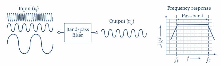
Figure 3. Waveforms and frequency response for a bandpass filter. Image used courtesy of Amna Ahmad
Resonance can be used to allow one band of frequencies to be delivered to a load. The simplest circuits are a series resonant circuit and a parallel resonant circuit. Bandpass filters are typically used in communications applications to tune frequency bands.
In a series resonant circuit, capacitance has high reactance below the resonant frequency, and inductance has low reactance below the resonant frequency. Above resonant frequency, the capacitance has a low reactance, while inductance has a high. At the resonant frequency, the inductive reactance equals capacitive reactance, and maximum current passes through the load resistor. Using a bandpass filter, the band of frequencies passed to the load includes those between the half-power points of the curve.
The same bandpass circuit can be obtained using a parallel resonant circuit in parallel with the load. Below resonant frequency, the inductive reactance is low, and the current bypasses the load. Above resonant frequency, the capacitive reactance is low and shunts the current around the load. At the resonant frequency, the impedance of the parallel circuit is at its maximum value, causing the maximum current flow to the load. Resistance limits current flow in the circuit when either the capacitive or the inductive reactance equals zero. Bandpass filters are used in the reproduction of audio frequencies in stereo speakers. Typical stereo speaker systems have three loudspeakers: small (tweeter), midsize, and large (woofer). A crossover network is an arrangement of bandpass filters to route the appropriate signal to the proper loudspeaker.
Band-Stop (Notch) Filter
A band-stop frequency filter is a filter that reduces signals between selected frequencies. Using a band-stop filter, selected frequency bands can be prevented from reaching the load, as shown in Figure 4.
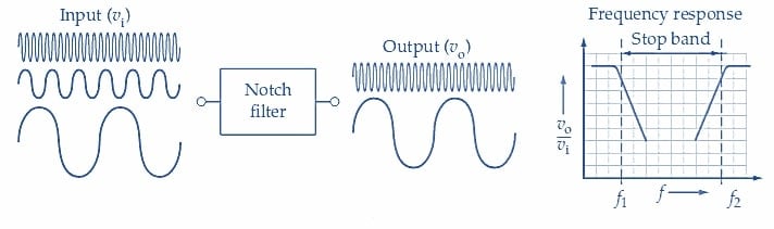
Figure 4. Waveforms and frequency response for a notch filter. Image used courtesy of Amna Ahmad
Filtering selected frequency bands is accomplished using a series/parallel resonant circuit designed with a stop band. Band-stop filters are typically used in applications to remove a certain frequency, such as 60 Hz.
When a series resonant circuit is placed in shunt with the load resistor, the series resonant circuit, at its resonant frequency, will short most of the current around the load resistor. Since this arrangement acts as a short circuit, a resistor is used to limit the current flow from the source to a safe level.
Current flow from the source can also be limited by placing a parallel resonant circuit in series with the load. At resonance, placing a parallel resonant circuit in series with the load presents a very high impedance to the source, limiting current flow through the load. The maximum current flow in this circuit is limited by the load's value and the source voltage's value.
Key Takeaways of Frequency Filters
Frequency filters are combinations of inductors, capacitors, and resistors that make it possible to select or reject bands of frequencies. The characteristics of different combinations of these components make it possible to select broadcasts from one radio or television station while excluding others. Frequency filters are generally used for power applications (to eliminate harmonics) and communications applications (to attenuate undesirable frequency signals).
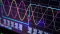
Featured image used courtesy of Adobe Stock