Facebook
 Google
 GitHub
 Linkedin
Predicting and Controlling Thermal Runaway in High-Voltage Power Modules
In this article, we take a system-level look at how thermal runaway begins, propagates across multi-module converters, and how engineers can model, predict, and prevent instability.
In high-voltage IGBT and SiC modules, thermal runaway is not just a case of the junction temperature going beyond safe limits, but it represents the escalation of a positive electrothermal feedback loop in which increasing temperatures also increase electrical losses, and these losses generate even more heat as they increase.
Once the system's ability to dissipate heat is overpowered by this feedback, the converter changes from handling manageable temperature increases into self-accelerated instability. With this transition, it can be easy to distinguish between a system that is experiencing thermal stress and one experiencing genuine runaway conditions.
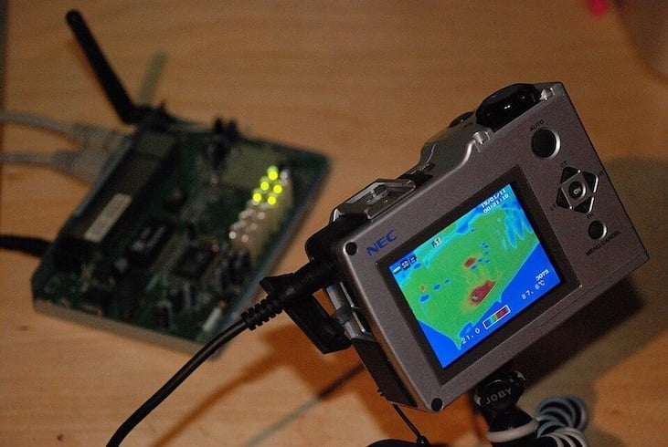
Figure 1. Infrared thermography image illustrating localized hot spots in a PCB, used here to visualize the risk of thermal runaway. Image used courtesy of Wikimedia.
Leakage currents, switching losses, and conduction resistance follow predictable patterns at moderate temperatures. However, as the junction temperature surpasses the upper limits, in cases where minor temperature changes trigger significant increases in loss, these parameters enter nonlinear regions.
For instance, a temperature increase in SiC MOSFETs results in higher reverse conduction losses and IGBTs' tail current that rises with temperature, while dielectric leakage may increase exponentially. Under these conditions, the rate at which these losses increase steeply with temperature results in a curve where the generated heat overwhelms the cooling system's ability to dissipate heat.
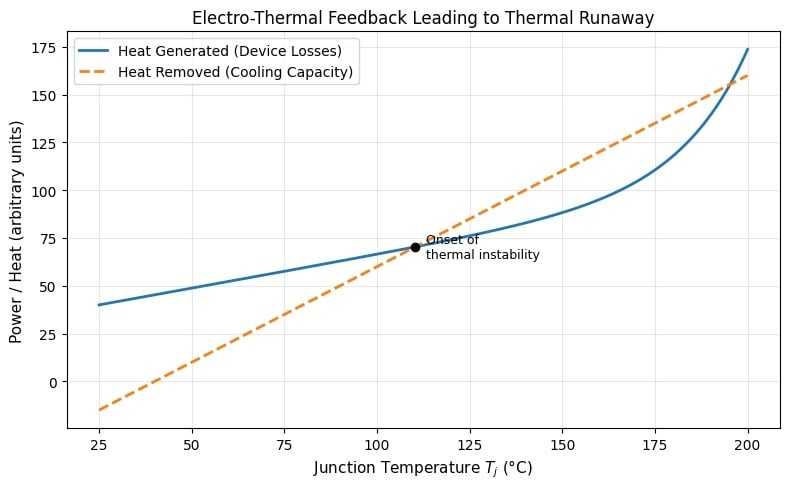
Figure 2. Conceptual electrothermal feedback curve of a power module, showing the onset of thermal runaway. Image used courtesy of the author.
As illustrated in Figure 2 above, the power module stays in a stable condition as long as its ability to dissipate heat surpasses the heat it produces. When there is a rapid increase in heat from losses compared to what the cooling system can handle, the feedback loop becomes positive, leading to an unstoppable rise in temperature.
Before looking at how thermal runaway can be predicted and controlled, it is essential to understand the difference between thermal imbalance and instability, nonlinear effects that, when combined, one module cannot maintain equilibrium, potentially causing stress to the close components, resulting in a system-level instability.
Understanding Thermal Balance and Thermal Instability
Thermal balance, the equilibrium state in which heat is dissipated at the same rate as its generation, is an aspect that ensures stability in power modules, as the junction temperature remains steady at a predictable operating point.
When this thermal balance is disrupted, either by higher losses in the power module or reduced cooling capabilities, the system enters a state where temperature begins to rise, and if left unchecked, the system may reach a point of thermal instability where the thermal regulation mechanism fails, and the temperatures rise uncontrollably.
With the heat source resulting from conduction and switching losses, the thermal impedance from junction to coolant determines the cooling capacity. As cooling fun, pump, and TIM degrade, there is impedance that reduces the gap between stable operation and runaway.
Looking at the conditions that trigger thermal instability, SiC devices under high blocking voltage face a rapid growth in leakage current, creating unexpected heat even during minimal switching. Another factor to be considered as a potential cause of instability is solder and interface degradation, which suddenly increases θJC, concentrating heat at the die.
Localized hotspots may also result from parasitic coupling in series-connected or stacked power models where there is uneven voltage sharing, and when all these effects are combined, they push the power module to a point where the cooling system cannot restore equilibrium.
What are some of the early indicators of thermal instability in power modules? One of the early signs is the compression of the active safe area (ASO), which occurs as the temperature curve resulting from losses steepens, reducing the allowable current and switching stress.
Another critical indicator is the drift in temperature when there are PWM operations, where instead of a stable steady state, the temperature rises cycle by cycle, indicating that the generated heat can no longer keep pace with its cooling.
Heat Propagation in Multi-Module Configurations
Multi-level converters rely on the precise sharing of voltage between modules, in which, when one module heats up beyond its designed operating range, the other modules begin to face some destabilizing effects. The heat buildup can be propagated through the mechanical structure of the power module through to other sub-modules, raising their junction temperatures even in constant electrical loading.
Local hotspots can develop from shared heatsink, base plates, and through laminated busbars, where heat can spread longitudinally, spreading to the neighboring components. Another effect is capacitor heating that changes the equivalent series resistance (ESR), resulting in localized thermal stress. This chain reaction means that a single module can compromise the entire converter arm.
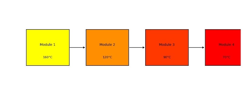
Figure 3. Conceptual illustration of thermal runaway propagation across the module. Image used courtesy of the author.
In parallel converter legs, thermal instability often emerges from current imbalance, and when one module heats up, current is unevenly distributed to the other modules. The hot modules draw more current due to increased channel resistance, affecting the already stressed device. The uneven current redistribution can cause a loss of asymmetry feedback into the system control. In this case, the temperature-dependent changes in switching or conduction loss can change the behaviour of the control loop, causing the imbalance.
Predictive Simulation Framework for Runaway Detection
Thermal runaway prediction requires a more static thermal analysis where engineers need to evaluate the interaction of losses, temperature, and cooling over time. Modern high-power IGBT and SiC systems rely on electro-thermal co-design, linking power loss calculations to time-dependent thermal models to determine whether the components reach steady state operation or diverge towards instability.
To accurately predict thermal runaway, we can describe the evolution of the junction temperature during switching, conduction, and leakage losses that are converted to heat, which flows through the thermal impedance of the power module. As represented in the equation, the heat being removed depends on the cooling architecture and the limit of the material, and since losses rise with temperature, the system becomes nonlinear.
The general equation of nonlinear electro-thermal feedback and runaway prediction can be implemented by considering the junction temperature at the semiconductor die at time t, the incoming ambient or coolant temperature Tα, the total power loss as a function of temperature Ploss(Tj), and the time-dependent thermal impedance Zθ(t).
$$T_j(t) = T_a + P_{loss}(T_j)~\times~Z_{\theta}(t)$$
We can then interactively model the next step by considering the feedback loop resulting from the temperature rise to understand how the loop produces thermal runaway when it is past the cooling capabilities of the power module. In the model, the new temperature is dependent on the previous temperature to create the feedback loop, and it considers the simulation time step Δt.
$$T_j(t~+~\Delta t ) = T_a + P_{loss}( T_j(t))~\times~Z_{\theta}(t~+~\Delta t )$$
Using the runaway criterion, the exact point at which the electro-thermal feedback of the device becomes positive instead of negative. In this case, the criterion defines that for every slight increase in the junction temperature, there is production of additional heat that the cooling system cannot dissipate. Leakage current in SiC MOSFETs and IGBT tail current all contribute to a larger sensitivity of the losses to an increase in temperature.
The power module is in a state of equilibrium, and the cooling can compensate if:
$$\frac{dP_{loss}}{dT_j}~\times~Z_{\theta}(t) < 1$$
The power module is on the edge of stability if:
$$\frac{dP_{loss}}{dT_j}~\times~Z_{\theta}(t) = 1$$
Finally, the power module enters thermal runaway, and the feedback becomes positive if
$$\frac{dP_{loss}}{dT_j}~\times~Z_{\theta}(t) > 1$$
Designing for Stronger Thermal Instability Resistance
When designing a reliable converter that can resist thermal instability, thermal runaway can be tackled in three ways, which include improving the ability of the converter to dissipate heat by lowering thermal impedance, reducing the growth of power loss with temperature increase, and adding control and protection for early detection of thermal instability.
| No. | Design Category | Engineering Action | Technical Purpose |
| 1. | Device Selection | Choose low leakage device and with controlled tailed current behaviour | Reduces temperature-sensitive loss growth. |
| 2. | Thermal Mass and Direct Cooling | Add heat spreaders or use direct DBC cooling for high energy pulses | Lowers transient and slows the rise of temperature for control reaction time. |
| 3. | Sensing Architecture | Install multiple sensors on die junction and external surfaces | Enables accurate temperature tracking and hotspot detection.
|
| 4. | Protection and Control Strategy | Define tired derating, phase shedding, and coordinated shutdown logic. | Provides active suppression of runaway and limit failure. |
Table 1. Practical checklist for the design of a strong thermal instability resistant converter.
Heat dissipation design can be improved by employing the use of high-performance TIMs, increasing thermal capacitance, and reducing the effective junction to ambient steady thermal resistance by 30% compared to the baseline design in the initial sizing. When it comes to material and layout strategies, the busbars can be segmented to reduce longitudinal heat spread and use dedicated heatsinks for each module rather than a single continuous plate.
Using multipoint sensing and implementation of rate of rise algorithms, not just absolute temperature, fast detection can be possible for timely corrective measures. Control aspects, such as coordinated shutdown in overheating events, can be implemented to avoid asymmetric turn-off that could cause large transient currents.
Overall, power engineers need to treat thermal instability as a system-level challenge that needs close attention for power module reliability. By designing with margin, implementing predictive monitoring, and validating under degraded conditions, converters can remain stable even in the most demanding mission profiles.